Download
1 / 34
340 likes | 472 Views
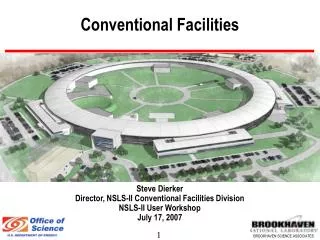
PAC Review CONVENTIONAL FACILITIES AND SITING A. Enomoto, V . Kuchler, J. Osborne. Outline CFS Introduction Geotechnical Conditions and Construction Methods Description of CFS Cost Drivers Americas and European Design CFS Schedule Summary Asian Design – A Enomoto.

E N D
PAC Review CONVENTIONAL FACILITIES AND SITING A. Enomoto, V. Kuchler, J. Osborne
Outline • CFS Introduction • Geotechnical Conditions and Construction Methods • Description of CFS Cost Drivers • Americas and European Design • CFS Schedule • Summary • Asian Design – A Enomoto
CFS Introduction and Regional Overview • Overall Siting Approach was to Initially Identify a “Sample Site” in Each of the Three Global Regions • Americas and European Sites Still Considered “Sample Sites” • Asian Region has Identified Two “Candidate Sites” • All Regions Used the Same Beamline Lattice Design • Underground Enclosures were Tailored to Meet Local Site Geologic and Topographical Conditions • Local Conditions Also Affected the Type of HLRF System Used • Americas and Europe Used the Klystron Cluster System (KCS) • Asia Used the Distributed Klystron System (DKS)
Regional Geotechnical Conditions and Underground Construction Methods (1) • Americas Region • Sample Site Centered on Fermilab • Uniform Surface Elevation Supports Surface Buildings • Uniform Galena-Plattville Dolomite Limestone Strata • Tunnel Depth ~130 m • Main Underground Access by Vertical Shaft • TBM Excavation Method Used for Main Tunnel Drives • Drill and Blast Excavation Method Used for Shafts, Widened Enclosures and Caverns • Widened Enclosures and Caverns do not Require Arched Ceilings • Klystron Cluster System (KCS) HLRF • Most RF Equipment is Located in Surface Buildings at Shaft Access • Electrical Equipment, Cooling Towers and Cryo Plants Located on the Surface at Shaft Access
Regional Geotechnical Conditions and Underground Construction Methods (2) • European Region • Sample Site Adjacent to Existing CERN Laboratory • Relatively Uniform Surface Elevation Supports Surface Buildings • Uniform Molasse Rock Strata • Tunnel Depth 100 - 150 m • Main Underground Access by Vertical Shaft • TBM Excavation Method Used for Main Tunnel Drives • Roadheaders or Rock-Breakers Used for Widened Enclosures and Caverns • Traditional Excavation Equipment and Special Ground Support Measures Used for Shaft Construction • Widened Enclosures and Caverns will Require Arched Ceilings • Klystron Cluster System (KCS) HLRF • Most RF Equipment is Located in Surface Buildings at Shaft Access • Electrical Equipment, Cooling Towers and Cryo Plants Located on the Surface at Shaft Access
1.7.1 Civil Engineering – Americas and European Regions (2) European Region Sample Site at Dubna Americas Region Sample Site at FNAL European Region Sample Site at CERN
1.7.1 Civil Engineering – Americas and European Regions (3) • Regional Differences Between the Main Linac Tunnel Cross Sections – Americas Region • Tunnel Diameter • Americas Cross Section is Smaller (5.0m vs. 5.2m) • Ventilation Systems • Longitudinal System for the • Americas Tunnel • Air Supply Ducts in Floor Slab • Tunnel Used as Return Duct • Services & Cables in the Concrete • Invert • Electronic Racks and Shielding • Space for Waveguides
1.7.1 Civil Engineering – Americas and European Regions (4) • Regional Differences Between the Main Linac Tunnel Cross Sections • Tunnel Diameter • European Cross Section is Larger (5.2m and 8.0m vs. 5.0m) • Ventilation Systems • Transversal Ventilation System with • Longitudinal Ducts at Tunnel Crown • Services & Cables in the Concrete • Invert • Avoided in European Region • Electronic Racks and Shielding • Space for Waveguides • Less Space for European • Layout, but, as needed, • Space can be made • Available
1.7.1 Civil Engineering – Americas and European Regions (5) European Region Tunnel Cross Section (Looking Upstream e- Linac) Americas Region Tunnel Cross Section (Looking Downstream e- Linac)
1.7.1 Civil Engineering – Americas and European Regions (6) Americas Region Interaction Region European Region Interaction Region
1.7.1 Civil Engineering – Americas and European Regions (7) Damping Ring Cross Section
1.7.1 Civil Engineering – Americas and European Regions (8) • Tunnel Lengths for Both Regions are the Same Based on the Same Machine Lattice • The Americas Region Used the Same Diameter TBM for Main Tunnel Drives and Drill and Blast Methods to Enlarge Enclosure Areas as Needed • The European Region Uses a Larger Diameter TBM where Technical Equipment Requires a Larger Dimensional Space • All Service Tunnels for Both Regions Use a Uniform Diameter TBM
1.7.1 Civil Engineering – Americas and European Regions (9) Americas Region European Region
1.7.1 Civil Engineering – Americas and European Regions (10) • Americas Region • Areas of Refuge are Provided • All Non-TBM Construction is • Considered a Cavern • Fire-Protected Connections are • Required for Shaft Access • Volumes for Sources are Mostly • Considered BDS • Americas Interaction Region • has a Larger Footprint • Shaft Construction Extends to • Tunnel Floor Level • Shaft Base Caverns do not • Include Shaft Volumes • European Region • Areas of Refuge are Not Needed • Some Minor Tunnel Widening is • not Considered a Cavern • Protected Shaft Access is not • Required • Volumes for Sources are • Considered as a % of Total • European Interaction Region is • More Compact • Shaft Construction Extends to • Top of Base Cavern • Shaft Base Caverns does Include • Shaft continuation Volumes
1.7.1 Civil Engineering – Americas and European Regions (11) Americas Region European Region
1.7.1 Civil Engineering – Americas and European Regions (12) European Region Americas Region
1.7.1 Civil Engineering – Americas and European Regions (13) Americas Region Surface Structure Summary and Typical Planat Main Linac Shaft
1.7.2 Electrical – Americas Region (1) Americas RegionKCS Power Load Table in MW
1.7.2 Electrical – Americas Region (2) Americas Region Electrical Single Line Diagram
1.7.2 Electrical – Americas Region (3) Americas Region Electrical Single Line Diagram at Central Region
1.7.3 Air Treatment – Americas Region (1) • Two Separate Ducted Air Supply Systems Provide Conditioned Air to the Tunnel Enclosures • General Supply Air with 20% Fresh Air • Emergency Supply Air to Areas of Refuge (AOR) When Needed • The Tunnel Enclosure Serves as the Air Return to Ducted Returns at Each Shaft • Conditioned Supply Air will Maintain Tunnel Air Temperatures at 86oF (30oC) – Temperature Stability +/- 1oC • Damping Ring and BDS have Additional Fan Coil Units to Maintain Tunnel Temperature Due to Addition Heat Loading and Stricter Temperature Tolerances +/- 0.1oC
1.7.3 Air Treatment – Americas Region (2) Americas Region Typical Air Treatment Schematic
1.7.4 Piped Utilities – Americas Region (1) • Tunnel and Enclosure Groundwater Inflow and Condensate Drainage Estimated as 21 m3/h/km • Duplex Sumps Discharged Through Shafts • 132 in Main Linac • 121 in Central Region and IR • 32 in Damping Ring • Surface Holding Tanks will Provide Monitoring Capability Prior to Discharge • Sprinkler Systems Throughout Underground Enclosures and Surface Buildings • Domestic Water and Sanitary Facilities Typically at the Base of Shafts and in Surface Buildings
1.7.5 Process Cooling Water – Americas Region (1) Americas RegionKCS Heat Load Table by Area System in MW
1.7.5 Process Cooling Water – Americas Region (2) Americas Region Typical Process Cooling Water Schematic
1.7.5 Process Cooling Water – Americas Region (3) Americas Region Chilled Water Schematic at Central Region
1.7.7 Safety Equipment – Americas Region (1) • Based on Requirements in National Fire Protection Association (NFPA) Standard for Subterranean Spaces, 2005 Edition • Verified Single Main Linac Tunnel Solution • Supported by Two Studies Conducted by Hughes Associates, Inc. • Code Analysis and Recommendations • Single Tunnel Analysis Using Fire Dynamics Simulator (FDS) which is a Computational Fluid Dynamics Program Developed by the USA National Institute of Standards • Personnel Egress • Hazardous Equipment and Shaft Elevators Protected by 2 hr. Fire Rated Walls and Doors • Main Linac Tunnel Serves as Escape Route • Emergency Lighting, Illuminated Exit Signage and Directional Signs • Automatic Sprinkler Protection • Addressable Fire Detection System
1.7.7 Safety Equipment – Americas Region (2) Plan Views at Shaft Base Caverns and Areas of Refuge
1.7.7 Safety Equipment – European Region (3) • Based on European, French and Swiss Safety Requirements • Single Main Linac Tunnel Solution • Avoiding Refuge Areas (Alcoves) Offering No Protected Exitway • Transversal Ventilation System • Tunnel Divided in Compartments Separated by Fire Doors and Fire Walls Every ~ 500m • Negative Pressure Created in Compartment Affected by Fire, Positive Pressure in Adjacent Compartments • Prevention of Smoke Propagation from One Compartment to the Next • Emergency Lighting, Illuminated Exit Signage and Directional Signs • Extensive Fire Safety Study Conducted for CLIC, Applicable for ILC
Construction Schedule – Americas and European Regions Courtesy M Gastal e+ BDS (2.25km) e- BDS (3.33km)
Summary • Regional Conditions have had a Large Impact on the ILC Conventional Facilities Design • In Both the Americas and European Regions Civil Design was Primarily Completed by In-House CFS Personnel Supported by Outside A/E Consultants • In the Americas Region a Complete Mechanical and Electrical Design was Completed by Outside A/E Consultants Supported by CFS In-House Personnel • Compared to the RDR the Overall Design Maturity has Greatly Improved in All Regions