Download

1 / 29
290 likes | 496 Views
High Speed Digital Systems Lab Electrical Engineering Department, Technion. Sub- Nyquist Sampling Expander Module. Winter/Spring 2010. Supervisors : Moshe Mishali, Ina Rivkin Students : Amir Bishara, Morad Awad. Agenda. Part A Reminder Last time Completing Part A NCO Part B Goals

E N D
High Speed Digital Systems Lab Electrical Engineering Department, Technion Sub-Nyquist Sampling Expander Module Winter/Spring 2010 Supervisors : Moshe Mishali, Ina Rivkin Students : Amir Bishara, Morad Awad
Agenda • Part A Reminder • Last time • Completing Part A • NCO • Part B • Goals • The Development process • Migrating between FPGA cards • Changes in architecture • Simulations • Results • Project outcome
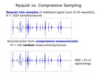
Memory Reminder Expand 1:3 CTF (Support recovery) Analog Back-end (Realtime) DSP (Baseband) Analog Hardware Detector Frequency domain elaboration: 1 -10Mhz 10Mhz 2 3 1 2 -10Mhz 10Mhz -30Mhz -10Mhz 10Mhz 30Mhz 3 -10Mhz 10Mhz
Last Time • Completed: • Algorithm • Architecture • Design • Implementation (VHDL) • Testing
Single Channel Architecture Init Cont. Filter Modulation Sync Filter Modulation Filter
Completing part A • Inaccurate results with real data, but good with synthetic data • Improve testing environment to have automatic tests for all modules • All modules work as expected • System level problem • Use MATLAB to perform different parts of the algorithm • Problem with the modulation • The modulation module doesn’t produce an accurate cos/sin signals
NCO • Use Altera’s MegaFunction to produce the cos/sin signals • The modulation module uses this component to produce the cos/sin signal • NCO issues • Can choose between 4 architectures • To get full accuracy the VHDL needs to be manually modified
Part B : Goals • Running the system successfully on the FPGA • Successful integration (logic level) with the DSP and CTF blocks
Development Process • Integration with the architecture team • Migrating to the new board • More resources • Faster • Meant to be used in the future • Changes in architecture • To save resources • Changes in design • To meet timing constraints • Adapt the testing environment to the architecture team environment • Testing
Migrating to the new board • Why? • More resources • Faster • Meant to be used in the future • Issues : • The card wasn’t responsive • Created new ProcWizard project • Changed architecture team software
Changes in the architecture • Why? • Saving resources • Solving problems arising at hardware debugging • Changes: • NCO module is taken out from modulation module • Made global to all channels • Add logic to control NCO phase
cos/sin generator Set Phase to zero
Changes in design • Why? • To meet timing constraints • How? • Break the combinational logic using pipeline • Convert non-optimized generic code to specific code • Where? • Multiplication + addition block • Generic code for addition • FIR filter , Polyphase • Long Muxing paths
Adapting the testing environment • The architecture team expects different format for input files • Outputs different format for output files • VHDL code converts between the formats • Small modifications from the files at part A
FPGA instead of MODELSIM Showing the results Preparing the input System Matlab Matlab FPGA Simulation Matlab Simulation DSP אותות משוחזרים Expander -FPGA תמך שהתגלה CTF Interfaces Added Testing • Testing environment diagram Results
Results • Several synthetic inputs were tested • Three different real input signals were tested • fm259_252_sin824_809 • fm259_252_am_872.697 • am_872.697_sin824 • All tests were successful • Integration team was able to: • Produce same results independently on FPGA using the new architecture • Run logic simulations of the Expander with DSP and CTF successfully
Demonstration • am_872.697_sin824
Improvements and future development • For future expansion : • Create a new module that represents a single output channel • Contains a modulation module and Polyphase module • Gets modulation signal as input • Mid channel “modulation” signal is 1 • Allows changing expansion factor (now is 1->3) easily • Add input signal to Expander system that allows changing modulation frequency at runtime • Make modulation phase shift register changeable at runtime • Resources sharing: • Make module that holds filter coefficients • Each filter requests for coefficients • Can reduce coefficients memory by a factor of 12
Project outcome • MATLAB simulations files for the algorithm • VHDL code implementing the design • VHDL + MATLAB code for testing environment • Two project books • User Manual for changing configurations and testing