Download
1 / 11
110 likes | 236 Views
Eli Baransky & Gal Itzhak. Sub- nyquist radar sensing. Basic Model. The pulse shape is known (usually gaussian ), if we limit ourselves to work In G(f)’s support, then we can calibrate to:. Our goal is to retrieve { a l ,t l }. . Two-Phase Reconstruction.

E N D
Eli Baransky & Gal Itzhak Sub-nyquist radar sensing
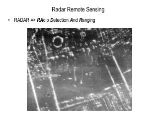
Basic Model The pulse shape is known (usually gaussian), if we limit ourselves to work In G(f)’s support, then we can calibrate to: Our goal is to retrieve {al,tl}.
Two-Phase Reconstruction • The first stage is analog compression using standard analog devices • (Filters, splitters, ADC). • The second stage is a digital recovery algorithm, implemented on FPGA. • In order to understand the first stage, we begin by examining • the second stage. Signal Generator Wave Generator FPGA Analog Pre Processing
Digital Recovery In all further discussion we restrict ourselves to discrete frequencies, integer multiples of 1KHz (the best we can achieve with T=1[ms] interval). Spectrum Estimation Algorithms We can re-formulate the problem in (1) as sum of exponentials problem, where k play the role of time, and {tl} play the role of the unknown frequencies. There are many known mature techniques to solve these kind of problems. We have focused on Matrix Pencil.
Digital Recovery Compressed Sensing Algorithms Another point of view on (1) is a sparse linear combination of a known basis. In general the basis is infinite, but assuming quantization of time we form a group of vectors: Where κ is a set of pre-determined Fourier coefficients. Formulating a matrix with un as its columns, we can approximate (1) by: We solve this problem using the well known OMP algorithm.
Comparing Approaches The greater part of our previous work was to determine which of the two algorithms performs better in our detection problem. As we know, the minimal number of data samples needed to recover the unknowns is |k|=2xL+1. To achieve noise robustness, we introduce an oversampling factor OS so |k|=2xOSxL+1. Matrix Pencil requires the set k to be chosen consecutively, while OMP allows the set to be chosen arbitrarily. We have tested both algorithms under many different parametric conditions.
Simulation Results Random OMP has better noise robustness, and therefore was selected
Analog Compression For OMP we require a distributed set of frequency samples (K). We need to devise an analog scheme that allows us to sample the signal at a sub-Nyquist rate, and still reconstruct the spectrum at the chosen frequencies. Multi-Channel Integrators Sum-of-Sincs Filtering Both schemes are impractical with given technology.
Analog Compression With our help, Idan developed a scheme that is a compromise between the two approaches – an analog filter bank that decomposes the signal into four different frequency bands. Each band’s width is ~200KHz, allowing us to sample it at 400KHz without aliasing. In practice we sample at 4MHz, which is 10x oversampling, allowing some noise robustness. Further frequency selection is performed digitally on FPGA. FPGA Low-Rate ADC Bandpass Filter [fi,fi+Δf] Lowpass Filter [0,Δf] Bandpass Filter [fi,fi+Δf] Lowpass Filter [0,Δf] Low-Rate ADC
Possible Problems • Splitter phase unbalance • Unideal BPF • Genearor Jitter/Phase Noise – Sinusoids have “dresses” in spectrum • Trade off of LPF – narrow transition band means signal “escapes” out of • interval. Wide transition band means we need to sample faster. • ADC jitter