Download
1 / 15
600 likes | 5.46k Views
THREE PHASE FAULT ANALYSIS WITH AUTO RESET ON TEMPORARY FAULT AND PERMANENT TRIP OTHERWISE. Submitted by:. Contents. Project overview Block diagram Transmission Line faults Comparator 555 timer Relay Schematic & Working of the project Advantages Applications Future scope Conclusion.

E N D
THREE PHASE FAULT ANALYSIS WITH AUTO RESET ON TEMPORARY FAULT AND PERMANENT TRIP OTHERWISE Submitted by:
Contents • Project overview • Block diagram • Transmission Line faults • Comparator • 555 timer • Relay • Schematic & Working of the project • Advantages • Applications • Future scope • Conclusion
Project overview • Three single phase transformers are wired in star input and star output having input 220 volt and output at 12 volt. • The contact relays which are used energized from the output of comparators in the event of fault conditions by tracking the input voltage conditions for each phase at the input of the comparators. • Two 555 timers are used, one in monostable and the other in astable mode to drive a power relay that handles the load. • A Set of switches are used to introduce LL fault, LG fault ,3L short to get the comparator output to drive both the relays to disconnect the load. • Short duration fault returns the load immediately while long duration shall result in permanent trip.
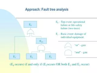
Transmission line Faults • Fault types include: • Single line to ground(LG) • Line to line(LL) • Double line to ground(LLG) • Three phase balanced
Comparator • op amps & comparators look very similar • But a comparator gives a logic output indicating the relative potentials on its two inputs • An op amp amplifies the differential voltage between its two inputs – and is designed always to be used in closed-loop applications
Contd.. • Potential dividers are connected to the inverting and non inverting inputs of the op-amp to give some voltage at these terminals. • Supply voltage is given to +V and –V is connected to ground. • The output of this comparator will be logic high (i.e., supply voltage) if the non-inverting terminal input is greater than the inverting terminal input of the comparator. • If the inverting terminal input is greater than the non-inverting terminal input then the output of the comparator will be logic low (i.e., gnd).
555 Timer • The 555 Timer IC is an integrated circuit (chip) implementing a variety of timer and multivibrator applications. • The original name was the SE555 (metal can)/NE555 (plastic DIP) and the part was described as "The IC Time Machine". • Depending on the manufacturer, the standard 555 package includes over 20 transistors, 2 diodes and 15 resistors on a silicon chip installed in an 8-pin mini dual-in-line package (DIP-8)
PIN DIAGRAM OF 555 • The 555 timer IC is a simple 8 pin DIL package IC. • It can: • be used as a monostable • be used as an astable • source or sink 100mA • use supply voltages of 5v to 15v • disrupt the power supply - use a • decoupling capacitor!
Relay • A relay is an electrically operated switch. • Current flowing through the coil of the relay creates a magnetic field which attracts a lever and changes the switch contacts. • The coil current can be on or off so relays have two switch positions and have double throw (changeover) switch contacts as shown in the diagram.
Contd.. • Relays allow one circuit to switch a second circuit which can be completely separate from the first. • For example a low voltage battery circuit can use a relay to switch a 230V AC mains circuit. • There is no electrical connection inside the relay between the two circuits, the link is magnetic and mechanical. • To drive relay through MC ULN2003 relay driver IC is used
Working of project • In this project two 555 timers are used 1 in monostable mode and other in astable mode. • When any push button is pressed for a short time the load is disconnected only for that period indicating a temporary fault. • If the push button is pressed for longer time then the astable timer s activated and it causes a permanent fault and disconnects the load permanently.