Download
1 / 58
580 likes | 582 Views
This seminar discusses the use of Glass Resistive Plate Chambers (RPCs) in the BELLE Experiment for measuring CP violation and muon detection. It covers the principles of operation, timing resolution, rate capability, gas mixtures, mechanical details, and assembly process.

E N D
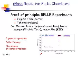
Glass Resistive Plate Chambersin the BELLE Experiment Daniel Marlow Princeton University Seminar at Rice University July 9, 1999 Rice University Seminar July 9, 1999
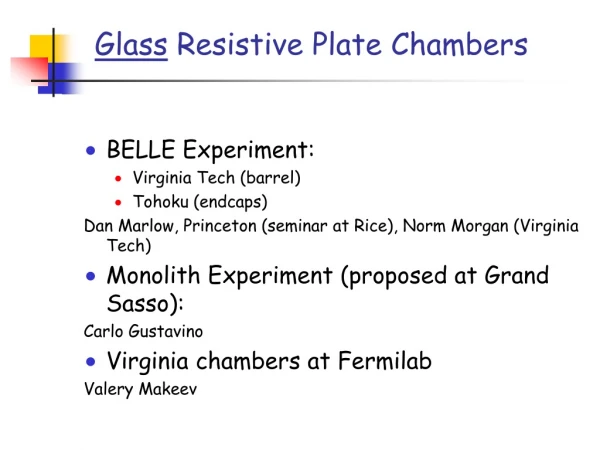
The BELLE KLM Group • KEK (K. Abe) • Osaka City University (Endcaps) • Princeton University (Barrel) • Tohoku University (Endcap) • Tohoku Gakuen University (Endcaps) • Virginia Tech (Barrel) Rice University Seminar July 9, 1999
Physics Motivation: Indirect CP Violation Measure CP violating KM phases by observing interference effects in the decay of neutral B’s. The `gold plated’ mode is very clean, both theoretically and experimentally. The mode is equally clean theoretically, yet still accessible experimentally. Rice University Seminar July 9, 1999
Physics Motivation The CP asymmetry changes sign when one goes from to .Depending on one’s level of faith in the theory, this provides a check or enhances statistics. Rice University Seminar July 9, 1999
Muon Detection The RPC array is also a key component when it comes to the traditional function of muon identification. • Functions: • Flavor tagging using leptons. Rice University Seminar July 9, 1999
The Detectives and their Detector Rice University Seminar July 9, 1999
Requirements • Modest position resolution: • Good detection efficiency • Low rates • Large ( ) area • Low materials costs • Easy assembly • Simple readout electronics Rice University Seminar July 9, 1999
India Ink Signal pickup (x) Glass plates 8 kV Signal pickup (y) India Ink +++++++++++++++ _ _ _ _ _ _ _ _ _ _ _ +++ +++++ _ _ _ _ _ _ _ RPC Principles of Operation Spacers A passing charged particle induces an avalanche, which develops into a spark. The discharge is quenched when all of the locally ( ) available charge is consumed. Before The discharged area recharges slowly through the high-resistivity glass plates. After Rice University Seminar July 9, 1999
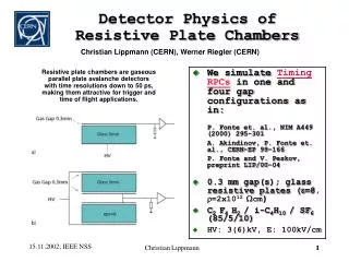
Leading Edge Time Resolution The timing resolution depends on the gas mixture, in particular on the amount of Freon. Freon 13B1 is no longer available. Rice University Seminar July 9, 1999
Plateau Curve 2 mm gap RPCs plateau at a fairly high voltage. By using both positive and negative supplies one can avoid the complications of a single-ended 7.5 kV HVPS. Note the slight falloff in efficiency well above the plateau. This effect is real and typical. Rice University Seminar July 9, 1999
Principles of Operation: I vs V Curve Glass RPCs have a distinctive and readily understandable current versus voltage relationship. • Low voltage • High voltage Rice University Seminar July 9, 1999
+++ +++++ _ _ _ _ _ _ _ Principles of Operation: Rate Capability As noted, each discharge locally deadens the RPC. The recovery time is approximately Numerically this is (MKS units) Assuming each discharge deadens an area of , rates of up to can be handled with 1% deadtime or less. This is well below what is expected in our application. Rice University Seminar July 9, 1999
Pulse Shape One interesting feature of RPCs is that the signal can be observed both using a pickup electrode and by viewing the light signal using a PMT. The pulses are large (~100 mV into 50 ohms) and fast (FWHM ~ 15ns) There is a very good correlation between the electronic and the light signal. Rice University Seminar July 9, 1999
+++ ++++++++++++++ _ _ _ _ _ _ _ _ _ _ _ _ _ Afterpulsing We observe a significant rate of afterpulsing. Typically the afterpulses are spaced by ~40 ns from the initial pulse (and other afterpulses). We believe that these pulses are caused by photons that escape the primary avalanche and initiate new streamers in a non-depleted region of the chamber. In some cases several afterpulses are observed Rice University Seminar July 9, 1999
Gas Mixture • Traditional Gas Mixture • 64% Argon : 6% Freon 116 30% Isobutane • Constraints • Safety: gas should be non flammable: • mixture ---> 30% Argon : 62% Freon :8% Butane • Environment: Freon 116--> Freon R134A • Cost: Isobutane ---> Butane “silver” Rice University Seminar July 9, 1999
Mechanical Details Each module comprises two RPCs and orthogonal sets of readout strips. In principle, a single RPC would suffice, but the double layer provides redundancy and reduces the effect of irreducible efficiency losses, such as the spacers. It is easily seen that if the single layer inefficiency is , the two-layer inefficiency will be Typically Rice University Seminar July 9, 1999
RPC Assembly at Va Tech Rice University Seminar July 9, 1999
RPC Assembly at Va Tech To reduce assembly time, extruded strips were used instead of “button-like” spacers. This also provided a natural “mouse maze” to ensure uniform distribution of the gas. Rice University Seminar July 9, 1999
Pickup Electrodes The 5-cm-wide readout strips form a ~50 ohm transmission line. Cu-strip/Mylar Laminate (Sheldahl) Rigid foam 5 mm Cu sheet (for current return) Rice University Seminar July 9, 1999
2.25 m 40 mm 1.7~2.5 m Barrel Module Outer Dimensions 240 req’d in all Rice University Seminar July 9, 1999
Endcap Module Outer Dimensions Ten wedge-shaped RPCs (two layers of five) are used in each endcap RPC supermodule. Rice University Seminar July 9, 1999
Outer Jackets The barrel modules were contained in a light-duty frame with 0.5 mm (20 mil) aluminum skins. This thin shell held the modules together and provided protection from the environment (RF, water, dust, etc.) but added no mechanical strength. Owing to the way in which they were installed, a more substantial frame was needed for the endcaps. Rice University Seminar July 9, 1999
Problems and Solutions • Problem: Ink layers thin enough to provide the appropriate sheet resistance are susceptible to large uniformity variations (i.e., gaps). • Solution: mix white ink in with the black to raise the bulk resistivity of the ink. A thicker, more easily controlled, layer could then be applied. • Problem: “Mouse Maze” popping. In early versions of the RPCs, the glue joints for the spacers came loose. This caused the glass to bow out and resulted in an inefficiency loss in the central parts of the RPCs. • Solution: increase the width of the glue joint. Rice University Seminar July 9, 1999
. . . Problems and Solutions • Problem: readout strip separation. In a number of cases the connection between the readout strips and the cables used to carry the signals off the modules came loose. • Solutions: • Institute more rigorous quality control during assembly. • Conduct post assembly conductivity tests using signal generator. • Rework as needed prior to installation. Rice University Seminar July 9, 1999
ReadoutElectronics • Requirements • Hit/no-hit readout • 2 us Level 1 trigger latency • Compatibility with BELLE DAQ • Simple operation mode for installation testing • Large (~45K) channel count • Low cost per channel • High density boards • Low power draw Rice University Seminar July 9, 1999
ReadoutElectronics to TDC to TDC Basic 24-channel building block Rice University Seminar July 9, 1999
ReadoutElectronics The BELLE DAQ uses the Lecroy 1877 pipelined TDC as a standard. To reduce the channel count, and to take advantage of the multi-hit capability of these TDCs, we have implemented a time-multiplexing circuit, which combines twelve strip channels into a single TDC channel. 1 2 to pipelined TDC 1/2 Xilinx 12 The encoding scheme incorporates a leading “FAST OR” pulse for timing as well as a trailing parity pulse. Each hit strip generates a transition at the appropriate time. Rice University Seminar July 9, 1999
ReadoutElectronics 8 channels to TDC from RPCs 48 channels Custom VME Backplane from RPCs 48 channels 96-channel 6U VME board Rice University Seminar July 9, 1999
ReadoutElectronics Each crate can handle up to 1536 channels. In the production system, the high-speed readout path is through FASTBUS TDCs. The VME system is used for slow control and diagnostics, although it can also be used as a low(er)-speed readout for module testing. Rice University Seminar July 9, 1999
Gas System Requirements/Considerations • Parallel connections preferred • Gas tends to be poisoned as it passes through an operating RPC • (Our) RPCs are not tolerant of large pressure differentials that would occur in a series connected system. • Large (~750) channel count • Low cost/channel. • Low space per channel. • Easy adjustment • Highly safe operation obviously desirable • Gas must be exhausted ~20 m above experiment (large ~40 mm pressure head due to weight of gas). Rice University Seminar July 9, 1999
Gas System In early versions of the system we found that with inexpensive valves it was very difficult to balance the flow if several chambers were connected to a single manifold. The basic problem was that the pressure drop across the control valves was not so different from the pressure drop across the RPCs. As a result adjusting one channel caused changes in the other channels. Given that all we wanted was approximately equal flows, it seemed that there must be a better way. Rice University Seminar July 9, 1999
Flow Resistors The solution turned out to be a simple device that we call a “flow resistor”. These are simply 10-cm-long SS tubes with 250 um diameter bores. They are available from Fischer Scientific for ~$2.00 each. Rice University Seminar July 9, 1999
Flow Resistors The flow resistors are quite linear and show quantitative agreement with Poiseuille’s Law, including the expected dependence. Rice University Seminar July 9, 1999
Digital Bubblers To eliminate the tedium of checking all 750 output bubblers (and the corresponding safety-relief bubblers) we have developed a “digital bubbler” that monitors the flow by electronically counting bubbles as they pass through inexpensive photogates. The circuit shown is a functional equivalent. The actual circuit is somewhat more complex. To reduce cost and to maintain flexibility, a custom multiplexing (64:1) ADC system was developed. Rice University Seminar July 9, 1999
Digital Bubblers: Scope Trace Less light More light As the edges of the bubble pass through the photogates, they refract the light, causing a decrease in intensity. Rice University Seminar July 9, 1999
Exhaust System The exhaust system, which provides a zero-pressure (with respect to ambient) return path for waste gas, is built mostly from commercial components. Rice University Seminar July 9, 1999
System Performance Some typical cosmic ray events. Getting hits on all 28 layers requires pretty good efficiency. Rice University Seminar July 9, 1999
System Performance Cosmic ray plateau curves. The benefits of having redundant layers are evident. Rice University Seminar July 9, 1999
Cosmic Ray Timing Spectra The 32 us range of the TDCs pulls in a lot of noise hits, but most of the signal events are contained in a narrow ( ) range around prompt. The timing errors are dominated by cable length variations (no corrections have been made). Rice University Seminar July 9, 1999
Position Resolution Fit residuals from cosmic-ray data. Miss distance (cm) Rice University Seminar July 9, 1999
A Major Problem Develops The first signs of trouble showed up shortly after installation and looked something like the plot to the right. The current from a chamber would “suddenly” show a dramatic increase. Given that there is a “pedestal” current resulting from the spacers, the true dark-current increase was in fact substantial. Rice University Seminar July 9, 1999
A Major Problem Develops • The problem started to show up almost immediately upon installation in June of 1998. • The number of high-current RPCs increased steadily over the summer. The failure rate increased dramatically in late August, forcing us to shut down the system pending a better understanding. • High current is a serious problem in glass RPCs (see next slide). Rice University Seminar July 9, 1999
A Major Problem Develops . . . High dark currents induce a significant IR voltage drop across the glass plates, which lowers the voltage across the gap, causing the chamber to slide off the efficiency plateau. Increasing the applied voltage doesn’t help since it merely results in increased dark current. The is what I like to call the classic “RPC Death Spiral”. Rice University Seminar July 9, 1999
A Major Problem Develops . . . The correlation between dark current and efficiency loss is readily apparent. Rice University Seminar July 9, 1999
A Solution Emerges . . . • After several weeks of study we determined that the problem was due to high levels of water vapor in the gas. • Although we were aware of this problem (even more severe problems occurred in the early days of our R&D when some of our collaborators used urethane gas tubing, which is highly permeable), we had incorrectly assumed that water would not permeate our polyethylene (Polyflow) tubing. • In fact we were susceptible to water contamination for the following reasons: • Low flow rates • Long (5~12 m) runs of plastic tubing. • Hot and humid weather during the Japanese rainy season. • Using published data for polyethylene, we were able to account for the ~2000 ppm concentrations of water vapor that we observed. Rice University Seminar July 9, 1999
A Solution Emerges . . . We replaced the long runs of polyethylene with copper (~5 km in all!) and flowed gas at the highest possible rate (~one volume change per shift). Slowly, but surely, the RPCs began to dry out. Rice University Seminar July 9, 1999
A Solution Emerges . . . We were greatly relieved to see an accompanying drop in the dark currents! Rice University Seminar July 9, 1999
A Solution Emerges . . . Although some residual damage remains, the situation is much improved. Rice University Seminar July 9, 1999
KLM PhysicsPerformance Muon detection efficiency for “Level 2” cuts. Monte Carlo Pion fake rate for “Level 2” cuts. Rice University Seminar July 9, 1999