Download
1 / 29
290 likes | 294 Views
A Hadron Calorimeter with Resistive Plate Chambers. Jos é Repond Argonne National Laboratory Presented by Andy White University of Texas at Arlington. LCWS 2006, Bangalore, India, March 9 – 13, 2006. Collaborators.

E N D
A Hadron Calorimeter with Resistive Plate Chambers José Repond Argonne National Laboratory Presented by Andy White University of Texas at Arlington LCWS 2006, Bangalore, India, March 9 – 13, 2006
Collaborators 197 Physicists 34 Institutes 9 Countries 3 Regions
HCAL R&D Goal Prototype section (PS) 1 m3 (to contain most of hadronic showers) 40 layers with 20 mm steel plates as absorber Lateral readout segmentation: 1 cm2 Longitudinal readout segmentation: layer-by-layer Instrumented with Resistive Plate Chambers (RPCs) and Gas Electron Multipliers (GEMs) Motivation for construction of PS and beam tests Validate RPC and GEM approach (technique and physics) Validate concept of the electronic readout Measure hadronic showers with unprecedented resolution Validate MC simulation of hadronic showers Compare with results from Scintillator HCAL Comparison of hadron shower simulation codes by G Mavromanolakis
Staged approach I R&D on RPCs Development of conceptual design of electronic readout Tests with cosmic rays and in particle beams II Prototyping of RPCs for prototype section (PS) Prototyping of all components of electronic readout for PS Slice test in particle beam III Construction of PS Detailed test program in Fermilab test beam IV Design of Hadron Calorimeter for ILC detector Done Planned for November 2006 Earliest in 2007 Started
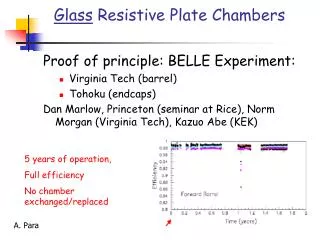
Status of RPC R&D Virtually all R&D completed
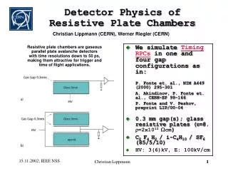
Pick-up pads Graphite Signal HV Gas Resistive plates Default RPC chamber designs for PS
Recent Tests in Fermilab’s MT6 Test Beam Signed MOU in December 2005 Dave Underwood spokesperson Started setting-up behind beam dump in January 2006 2 RPCs with 64 channels and VME readout (events in the two chambers can be correlated) → Chambers based on different design (1 vs 2 glass plates) 1 RPC with 32 channels and shift register readout (independent DAQ) Beam telescope with 4 scintillation counters → Trigger area ~ 4 cm2 Moved into beam on February 22 Took data for ~2 x 6 hours Beam = 120 GeV/c protons 4 second spill every 2 minutes Requested variation of beam intensity between 70 and 5000 Hz/cm2 Also took data with block of steel in front of RPCs T955
Experiences at MT6 • Safety • Trouble getting gas system approved by safety review committee • Committee requested - use of approved tanks • - use of gas fittings (worse) instead of water fittings (much better) • - detailed description of gas mixing procedure • Spent weeks in trying to accommodate safety committee • Environment • February was particularly cold and wet • Freon liquefied in tanks and gas lines (when outside beam area) • Roof leaks → puddles, high humidity • Beam intensity • Easily adjusted to requested values • Usually new setting established between spills (no beam losses for data taking!) • → Many thanks to FNAL beam crew for excellent performance • Results soon • Measurement of efficiency and pad multiplicity as function of particle rate • → Used fixed threshold, but ran with different high voltage settings • Measurement of correlation of pad multiplicity between 2 RPCs
Electronic Readout System for Prototype Section 400,000 readout channels Conceptual Design of Readout System I Front-end ASIC and motherboard II Data concentrator III Super Concentrator IV VME data collection V Trigger and timing system
Specification of system completed Document Written by Gary Drake (ANL) Released in September 2005 Contains all details of system Basis for design work of subsystems Counts 57 pages
Front-end ASIC… 64 inputs with choice of input gains RPCs (streamer and avalanche), GEMs… Triggerless or triggered operation 100 ns clock cycle Output: hit pattern and time stamp Abderrezak Mekkaoui James Hoff Ray Yarema Design work at FNAL Design work started in June, 2004 Prototype run submitted on March 18th 2005 40 unpackaged chips in hand Tests started…
Unpackaged chip housed on small test board Tests of ASIC at Argonne Built computer interface for test Wrote software for automated tests
Measurements across all channels in ASIC First Results a) All digital functions seem operational b) Detailed tests with injected charges so far look good Injected charge = 4.48 fC Threshold curve for Q = 2.83 fC Injected charge = 2.83 fC - T50 values uniform across all 64 channels - Overall small spread in T50 values - Slope of threshold curves uniform across all channels - Small spread in slopes - Fit to straight line satisfactory - Define T50 as threshold with 50% efficiency
Results as function of input charge Error bars = RMS of distributions 2nd Iteration of ASIC Prototype - Decrease of input sensitivity by x 10 – 20 Currently upper threshold corresponds to 7.6 fC Smallest RPC signals ~ 100 fC Noise from digital lines ~ 11 fC (preliminary) - Possibly decrease of serial line speed by x 10 Currently 10 times faster than 10 MHz clock speed - Other minor changes needed - Submission on May 22nd Redesign will start in late March Nice linear dependence!
Cooling… Chip consumes about 300 mW (measured) 144 chips/plane → 50 W/plane Thermal conductivity of steel not sufficient to dispose of heat Copper x10 better thermal conductivity than steel Consider replacing 4 mm support plates with copper plates Cost OK Magnetic properties not relevant for test beam Properties for EM and HAD showers similar Steel (16 mm) Steel (16 mm) RPC (8 mm) Copper (4 mm)
Front-end boards… 2 boards/chamber or 6 boards/plane 8 layer boards Overall thickness < 3 mm Functionality Houses ASICs (24) Provides readout pads for RPCs Routes signals to ASICs Distributes power and ground to ASICs Distributes clocks and control signals to ASCIs Routes output signals (LVDS) to receivers } Analog signals Design challenge } Slow control } Digital signals
Readout pads 1 Ground planes LVDS lines 2 3 4 Digital → analog crosstalk… Measurements with test board LVDS signals routed close to pads 4 different configurations Each with 4 different distances to the center of the pads First indicate cross-talk of ~11 fC, but more tests needed…
Data concentrators… Read out 12 ASICs (serial lines) Located on sides of section Can buffer events Distribution of trigger and timing (bus connection) Essentially FPGAs All transmissions in LVDS To Super concentrators Chip12
Super concentrators… Introduced by urge to reduce cost of back-end Reads out 6 data concentrators Located on side of module Similar design to data concentrator
Data collector… VME based system Each card reads out 12 super concentrators Need only 7 cards and 1 VME crate Investigating possibility of using CALICE-AHCAL back-end or Fermilab’s test beam DAQ system
Work by Lei Xia Study of rates… Simulation of response of 1 m3 prototype section to 50 GeV π+ Study of data rates in different components of the readout system System capable of handling ~10x more data than expected Examples… Readout speed 10 Mb/sec Average number of ASICs in a given data concentrator Number of ASICs in any data concentrator Number of ASICs in a given event
Mechanical Structure for PS CALICE builds versatile structure Absorber 20 mm Steel→ 1 X0 sampling 40 layers → 4 λI at 900 Recent simulation studies indicate that Tungsten with Thickness of 0.7 cm → 2 X0 sampling 58 layers → 4 λI at 900 might result in better PFA performance and safe on cost (coil) • Do we need to test a Tungsten prototype? • If yes, can we re-use the CALICE structure? • What is the optimum sampling depth for W? Questions
Mechanical Structure for ILC Detector Initiated study in context of SiD concept 3 barrels in z - to provide space for readout cables, gas supplies… - to minimize deflections along z and for modules in 900 position 12 modules in φ
Plates held in place by ‘picture frames’ space for routing cables… Gap between active areas approximately 2 cm Deflections everywhere smaller than 0.53 mm (If considering single barrel with supports only at the ends, largest deflection 44 mm)
Cost estimate for PS (M&S only) Probably Not needed 653,000 + 204,100 = 857,100
Time scales This part Is funded Only possible with additional funding