Download
1 / 16
160 likes | 250 Views
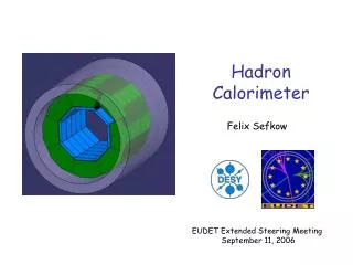
A Hadron Calorimeter with Resistive Plate Chambers. Jos é Repond Argonne National Laboratory. CALOR 2006, Chicago, June 5 – 9, 2006. Within the paradigm of PFAs. Role of calorimeter is to measure energy of neutrals ( γ ’s , neutrons and K L 0 )

E N D
A Hadron Calorimeter with Resistive Plate Chambers José Repond Argonne National Laboratory CALOR 2006, Chicago, June 5 – 9, 2006
Within the paradigm of PFAs Role of calorimeter is to measure energy of neutrals (γ’s, neutrons and KL0) Major challenge is to disentangle energy from charged and neutral particles in a jet Keeping the ‘confusion’ under control is more important than optimization for single particle resolution Requirements for the Hadron Calorimeter 1) Extremely fine segmentation of the readout → O(1 x 1 cm2 laterally, layer – by – layer longitudinally) → Large number of channels → requires multiplexing early on → reliable electronics located inside calorimeter 2) Located inside high – field coil → operation in high magnetic field → thin active element (cost of coil!) 3) Active element with large area → O(5,000 m2) → affordable technique (silicon most likely not possible)
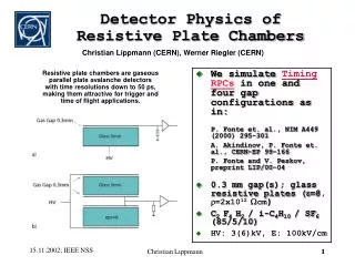
Pick-up pads Resistive Coating Signal HV Gas Resistive plates Resistive Plate Chambers No ageing ever observed with glass RPCs are… Simple, robust, cheap, quiet, well understood, reliable Adaptable to different requirements (TOF, high efficiency, large area…) μ Pick-up pads Can be small: O(1 mm) Can be stripes or pads
RPC: Design Choices for HCAL Resistive plates Glass with a thickness of 1.1 mm Commercially available Bulk resistivity ρ~ 4.7 · 1012Ωcm Resistive paint Surface resistivity σ~ 50 MΩ/□ Applied with silk screening techniques Gas gap Defined fishing lines → 1.2 mm Operation in Avalanche mode Gas mixture 95:5:0.5 = R134A:Isobutane:SF6 Readout pads Squares with an area of 1 x 1 cm2 Explored 2 different designs • Standard Design: AIR5 • 2 glass plates: cathode and anode Signal Pads Mylar sheet Resistive paint 1.1mm Glass sheet 1.2mm gas gap GND 1.1mm Glass sheet Resistive paint -HV Mylar sheet Aluminum foil B) ‘Exotic’ Design: AIR9 1 glass plate: cathode Readout pads serve as anode 1.6mm PC board Pad array 1.2mm gas gap 1.1mm Glass sheet -HV Graphite paint
RPC testscosmic rays and analog (=multi-bit) readout Measurement of MIP detection efficiency and streamer fraction Measurement of pad multiplicity for different MIP detection efficiencies (adjustment of threshold) Measurement of signal charges in avalanche and streamer mode
RPC testscosmic rays and digital (=single-bit) readout MIP detection efficiency versus threshold Comparison with exotic chamber Air9 chamber Pad multiplicity versus threshold
Sr90 source RPC MIP RPC testscosmic rays and digital (=single-bit) readout Noise rate versus threshold MIP detection efficiency versus rate
RPC testsparticle beams and digital (=single-bit) readout Tests at MTBF (FNAL) 120 GeV/c protons Set-up off beam axis → high particle multiplicity Unintentional! Trigger selects events from upstream showers Complicated correction procedure applied to determine efficiency and pad multiplicity Pad multiplicity MIP detection efficiency MIP detection efficiency versus trigger rate
Conclusions from RPC tests Large signals in avalanche mode Q in the range 100 fC ↔ 2 pC MIP detection efficiency very high εMIP close to 100% Pad multiplicity Lower with single-bit readout (short integration time) Standard design ~1.6 for an εMIP= 95% Exotic design ~ 1.1 for any εMIP Noise rate very low Nnoise < 1 Hz/cm2 Rate capability limited εMIPdrops for dN/dt > 50 Hz/cm2 Probably an underestimation Results from cosmic rays and test beams are consistent Chambers perform as required for the active element of a hadron calorimeter Chambers technology in hand to proceed to the construction of a prototype calorimeter
HCAL R&D Goal Prototype section (PS) 1 m3 (to contain most of hadronic showers) 40 layers with 20 mm steel plates as absorber Lateral readout segmentation: 1 cm2 Longitudinal readout segmentation: layer-by-layer Instrumented with Resistive Plate Chambers (RPCs) and GasElectronMultipliers(GEMs) Motivation for construction of PS and beam tests Validate RPC and GEM approach (technique and physics) Validate concept of the electronic readout Measure hadronic showers with unprecedented resolution Validate MC simulation of hadronic showers Compare with results from Scintillator HCAL Comparison of hadron shower simulation codes by G Mavromanolakis
Electronic Readout System for Prototype Section 40 layers à 1 m2→ 400,000 readout channels More than all of DØ in Run I I Front-end ASIC and motherboard II Data concentrator III Super Concentrator IV VME data collection V Trigger and timing system
The DCAL chip Specifications Developed to readout digital (hadron) calorimeters 64 inputs with choice of input gains → RPCs (streamer and avalanche), GEMs… Triggerless or triggered operation 100 ns clock cycle Output: hit pattern and time stamp History of development Designed by FNAL Prototype run submitted on March 18th 2005 → 40 unpackaged chips 2 chips mounted on test boards (wire bonded) Extensive tests began in July 2005… Redesign started for 2nd (and last) prototype submission → Decrease sensitivity of front-end Chips perform as expected
Remainder of the system Front-end boards Prototype boards tested Cross talk between digital and analog lines ~ 11 fC Better grounding schemes being investigated Data concentrator boards Readout 12 front-end ASICs Provide clock, trigger etc. to front-end Design work started Back-end Several options being evaluated 1) Use of CALICE Tile-cal back-end 2) Use of BTeV back-end at MTBF 3) Develop new system
Slice test Uses the 40 DCAL ASICs from the 2nd prototype run Equip ~8 chambers with 4 DCAL chips each 256 channels/chamber ~2000 channels total Chambers interleaved with 20 mm steel absorber plates Electronic readout system identical to the one of the prototype section Tests in MTBF beam planned for January 2007 → Measure efficiency, pad multiplicity, rate capability of individual chambers → Measure hadronic showers and compare to simulation Validate RPC approach to calorimetry Validate concept of electronic readout
Future Developments beyond the Prototype Section Resistive plate chambers More tests with exotic design (thinner!) Increase sensitivity to neutrons (gadolinium?) Long term tests (years) Electronic readout Finer segmentation of readout 1 x 1 cm2→ ? Finer timing resolution 100 ns → ? Thinner front-end boards ~ 3 mm → 1 mm? Higher multiplexing at front-end 64 → ? Channels/ASIC Higher multiplexing at back-end Token rings? Power pulsing of front-end Eliminate need for cooling Experience with prototype section will provide specific guidance Train structure of ILC beams Nominal baseline design 2820 bunches/train 307.7 ns bunch length 5 trains per second Collisions during 0.43% of running time Turn power down between collisions Power consumption negligible No cooling needed
Conclusions ► Application of PFAs require fine grained calorimeters ► Resistive Plate Chambers provide an excellent choice for the active media of the HCAL ► R&D on the chambers is completed with tests using cosmic rays as well as test beams ► Preparation for a slice test are under way ► Assuming a) the slice test is successful b) funding is being provided construction of 1 m3 prototype section will initiate in 2007 ► First results from tests in particle beams are expected by 2008 ► R&D beyond the prototype section will start soon…