Download
1 / 20
200 likes | 316 Views
HCAL Trigger Primitive Generator. Tullio Grassi University of Maryland September 2004. 8. 9. Syncronization FIFO WR RD. Trigger-Path (simplified) Case with Sum of FE-channels. Sum in E T. L1 Energy Filter. E T comp. Compr ession LUT. Linear and E T. 10. 7. 10. FE-link.

E N D
HCAL Trigger Primitive Generator Tullio Grassi University of Maryland September 2004
8 9 Syncronization FIFO WR RD Trigger-Path (simplified) Case with Sum of FE-channels Sum in ET L1 Energy Filter ETcomp Compr ession LUT Linear and ET 10 7 10 FE-link Muon INPUT LUT “NO-SHOWER” LUT take care of cases where showers can leak into a cell and incorrectly set the muon bit. BCID Muon bit 1 2
8 9 Syncronization FIFO WR RD Trigger-Path Case with Sum of FE-channels Sum in ET L1 Energy Filter ETcomp Compr ession LUT Linear and ET 10 7 10 FE-link Muon INPUT LUT “NO-SHOWER” LUT take care of cases where showers can leak into a cell and incorrectly set the muon bit. BCID Muon bit 1 2 HCAL PRS group should do some simulations to evaluate the efficiency before implementing it
8 9 Syncronization FIFO WR RD Trigger-Path Case with Sum of FE-channels Sum in ET L1 Energy Filter ETcomp Compr ession LUT Linear and ET 10 7 10 FE-link Muon INPUT LUT “NO-SHOWER” LUT take care of cases where showers can leak into a cell and incorrectly set the muon bit. BCID Succesfully initialized and read-back these LUTs. Storage of LUT data has been integrated with the prototype of the HCAL/EMu/Pixel Database Muon bit 1 2
9 8 Trigger-Path Case with Sum of FE-channels Sum in ET L1 Energy Filter ETcomp Compr ession LUT Syncronization FIFO WR RD Linear and ET 10 7 10 FE-link Muon INPUT LUT “NO-SHOWER” LUT take care of cases where showers can leak into a cell and incorrectly set the muon bit. BCID Muon bit Subtle changes in latency, depending on the settings (see next slides) 1 2
Latency of Synchronization FIFO WrClk RdClk FIFO content 0 0 0 0 1 1 1 1 0 1 Links established. Some of the FIFOs can be read “immediately” after writing.
Latency of Synchronization FIFO WrClk RdClk FIFO content Latency 0 0 0 0 1 1 1 1 0 1 n Links established. Some of the FIFOs can be read “immediately” after writing. Channel alignement with histograms of LHC structure
Latency of Synchronization FIFO WrClk RdClk FIFO content Latency 0 0 0 0 1 1 1 1 0 1 n Peak of jitter in one of the clocks. Links established. Some of the FIFOs can be read “immediately” after writing. Channel alignement with histograms of LHC structure
Latency of Synchronization FIFO WrClk RdClk FIFO content Latency 0 0 0 0 1 1 1 1 0 1 1 1 1 0 0 0 n n + 1 Peak of jitter in one of the clocks. Latency shift by one Links established. Some of the FIFOs can be read “immediately” after writing. Channel alignement with histograms of LHC structure
Latency of Synchronization FIFO • A possible solution requires a preset sequence of the FIFO: • make sure the FIFO is empty (reading without writing) • write 1 word • read and write continously • We have already tried it. • PROBLEMS • Read and Write controls are in different clock domains hard to control • Extra word increases latency Alternative solution: • we send the BC0 together with the data • monitoring FE-BC0 will show shift in latency • reset when this happens
Improved the Test Pattern Mode SEQUENCE One Test Pattern RAM per FE-link independent data per channel Load RAM s over VME Set a Pattern_Mode bit over VME two-level protection still use real FE-data Send a TTC broadcast (TestEnable) inject patterns now Run the FIFO patterns only once Use again real FE-data can place a peak on top of real pedestals ...but keep the data stored Time-stamps in the DAQ-data A VME-reg stores the BX# of the last TTC TestEnable broadcast t.b.d. MAIN USE: bld 904
Verification • We are implementing 64-bit CRC checksums to identify: • firmware downloaded into FPGAs • LUT content • Verification will be done comparing the calculation done in software and firmware. • CMS standard feature and codes ?
HTR-SLB-RCT integration in May 04 [Wisconsin] • One of the problems was related to the HTR • TTC messages [TX_BC0] did not reach the SLB • The problem has been identified in Maryland and fixed • Problem was the termination of TTCrx outputs
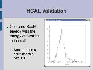
A technical look at TB04 Data • Event counter is reliable • SLINK event error rate [CRC] 0.025% • Bunch counter in HTR and DCC is consistently off-by-one (problem easily understood)
Trigger Primitives in the DAQ Path • While the role of the TP is to be sent to the RCT, the readout of the TP will be done through the DAQ path from HTR DCC as part of the event subfragment. • This functionality has been defined earlier, but was seriously tested. • HTR Rev4 starts up with “identity matrix” TPG Look-Up-Tables. • TPGs in the data fragment use resources • for any given channel :#TPG samples + #DAQ samples 20 • Tested in Maryland • Who is the customer ?
Slice integration tests at H2 • The testbeam environment has advantages over SX5 for initial integration tests. • High rate, structured, controllable source of particles • Easy access to adjust hardware • Focused time period for initial shakedown testing • End Oct 15th • HCAL + EMu • Goals: • Synchronization with separate readout • Combined readout in single EventBuilder • Unified Run Control and prototype DCS systems
Slice test: Goals • Prerequisite: subdetectors complete electronics validation before test • Both HCAL and EMu have had very successful testbeams already. • Goals: • Synchronization with separate readout • Combined readout in single EventBuilder • Unified Run Control and prototype DCS systems
Slice test: Trigger and TTC • EMu and HCAL will have separate TTCvi modules, with clocks derived from a common point. • Control signals will come from a common HCAL TriggerBoard. • Orbit signal (~930 clocks/orbit) from PCR will be used during spills. • Trigger sources: • Scintillator coincidence (external, standard trigger) • EMu TrackFinder/Sector Processor (“real” trigger) • “Sandwich board” on HTRs – trigger from calorimeter data
Integration at SX5(slice test 2) • The magnet test period (summer 2005) provides the most comprehensive opportunity to integrate multiple subdetectors before we go underground. • Several sub-systems will be installed in the final configuration and the detector will be closed for several months. • The disruptions and dangers of active installation will be paused. • Integration with central DAQ is possible using the pre-series system installed in the Green Barrack.
HTR board production Feb 2004: 3 HTRs received: small changes necessary July 2004: 6 HTRs assembled: assembly yield was low: 4/6 Sept 2004: sending out 6 HTRs to a different assembly house Full production before December 2004