Download
1 / 30
300 likes | 448 Views
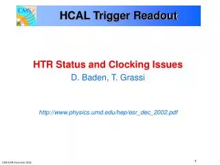
USCMS HCAL. Electronics Issues Drew Baden University of Maryland. SBS. CLK. D C C. CAL REGIONAL TRIGGER. H T R. H T R. H T R. 16 bits @ 80 MHz. TTC. 32 bits @ 40 MHz. QIE. CCA. GOL. QIE. QIE. CCA. QIE. GOL. QIE. CCA. QIE. FE/DAQ Electronics. DAQ.

E N D
USCMS HCAL • Electronics Issues • Drew Baden • University of Maryland
SBS CLK D C C CAL REGIONAL TRIGGER H T R H T R H T R 16 bits @ 80 MHz TTC 32 bits @ 40 MHz QIE CCA GOL QIE QIE CCA QIE GOL QIE CCA QIE FE/DAQ Electronics DAQ S-Link: 64 bits @ 25 MHz Trigger Primitives READ-OUT Crate Rack CPU 12 HTRs per Readout Crate, 2 DCC FRONT-END RBX Readout Box (On detector) HPD Shield Wall Fibers at 1.6 Gb/s 3 QIE-channels per fiber FE MODULE
“BIT3” board Slow monitoring over VME Commercial VME/PCI Interface to CPU FanOut board Takes TTC stream in Clone and Fanout timing signals HTR (HCALTrigger and Readout) board Spy output over VME FE-Fiber input TPG output (SLBs) to CRT DAQ/TP Data output to DCC DCC (Data Concentrator Card) board Input from HTRs Spy output Output to DAQ Readout VME Crate Front End Electronics TTC fiber Fiber 1.6 Gb/s F a n O u t VME CRATE B I T 3 H TR H T R H T R H T R D C C ... D C C 20m Copper 1.2 Gb/s DAQ Calorimeter Regional Trigger
HCAL Racks • HCAL will need 8 Racks • 2 crates/rack • ~200 HTR cards • ~3000 fibers and ~525 SLB with TPG cables • All I/O via front panels • Doors on front of rack required • Sufficient standoff to satisfy fiber curvature requirement • Keeps people from pulling out the fibers • Two 6U panels for cable/fiber support • Computer access in front of rack for fiber/TPG installation • Wireless in counting room? • Laptop/monitor/keyboard mounted somewhere close?
TPG Cable Issues • Amphenol skew-clear cables work @ 20m ok • Skew spec ~125ps @ 20m running at 1.2Gbaud • Eye pattern will survive, BER = 10-15 • Each cable carries 2 pair – need 2 cables per SLB connector • $100/cable + ~$150 for assembly/testing (custom connector molding) • Electrically these are very nice cables, but… • Formidable mechanical challenges – 6 of these beasts per HTR! • We are investigating quad cable, much thinner • Single cable, ~$180 for 20m • Would not require custom molding – much cheaper ~$30 for assembly • However…skew is almost x2 worse for 20m (230ps) • Amphenol spec says this will give 10-15 BER for 15m @ 1.6Gbaud • They were not clear about 1.2Gbaud – we will measure • If at all possible a 15m spec will: • Save money (~$100k) • Give breathing room on BER • Save 1 clock tick in L1 latency • Decrease mechanical risks on all boards
Rack Computer (dual Intel/Linux) 3U Air/Water Heat Exchanger 2U Air/Water Heat Exchanger 2U Cable Strain Relief 6U Cable Strain Relief 6U H T R H T R H T R H T R H T R H T R H T R H T R H T R H T R H T R H T R H T R H T R D C C D C C T T C T T C D C C D C C H T R H T R H T R H T R H T R H T R H T R H T R H T R H T R H T R H T R 9U 9U VME Rack Layout • 56U Total rack height, 55 used (Note: Can recover 3U by using 1U exchangers) • Rack computer (3U) • Air circulation has to be front → back ala DAQ crate • Recirculation/Monitoring (4U) • Extra Heat Exchanger • 2 VME crate zones: • Cable support (6U) • Front panel only • Fibers and TPG cables are formidable • VME Crate (9U) • Air/Water heat exchanger (2U) • Fan Tray (2u) • Power Supply zone (6U) • Cheaper, robust, safe, D0/CDF • Air transport issue here • Will have to build wire harness • Put A/C circuit breakers here? • Return air guide (2U) Recirculation Fan & Rack Protection 4U Air/Water Heat Exchanger 2U S B S Fan Tray 2U Fan Tray 2U Power Supply Zone 6U Return Air Guide 2U
Power Consumption Estimates • VME crate ~ 1.2kW (2 crates/rack only) • HTR 70W/slot • 7A @ 5V = 35W • 11A @ 3.3V = 33W • Includes 6 SLBs, but many cards will have fewer • 13 or fewer HTR/crate = 910W • Fanout card ~20W/slot • .5A @ 5V = 2.5W • 4.5A @ 3.3v ~16W • DCC ~ 60W/double slot • 5A @ 5V = 25W • 10A @ 3.3V = 33W • S-Link64 current draw is a wild guess • 2 DCC/crate = 120W • Add power for rack computer, monitor and fans to get rack power • 1kW max • Total power dissipated by entire rack ~3.5kW • Note current CMS power consumption ~2kW/crate, >6kW/rack
Production Schedule • Front-End • CCM Jun – Sep 03 • FE cards Jul – Oct 03 • RBX Aug 03 – May 04 • HPD deliveries from now until Apr 04 • HTR • Pre-production Jan 03, production Apr 03 – Sep 03 • DCC • Motherboards nearly complete, logic cards by Aug 03 • Awaiting final specs on S-Link64 • Fanout Card • Complete soon after QPLL, Q2/03
HCAL TriDAS Integration Status • First integration completed, summer 02 • FE HTR DCC SLINK CPU • All links well established • No obvious clocking problems • Work needed on synch monitoring and reporting • Improvements expected using crystal for TI refclk • Will always have TTC/QPLL clock as backup… • HTR firmware fairly mature • Switch to Virtex2 all but complete • TPG and BCID ready but not tested • To commence when next HTR version delivered and Wisconsin TPG boards delivered (est Q1 2003 for testing to commence) • Will be main effort when next HTR version arrives Jan 2003
HTR Production Schedule • Issues: • Parts availability for HTR • Stratos LC’s, FPGAs, etc., so far so good – should make schedule ok • QPLL not needed for HTR since we have a Fanout card per crate • Firmware requirements • Will learn a lot in 2003…very far along now
Integration Goals 2003 • Continued development of HTR and DCC firmware • Commission TPG path • Firmware requirements/logic, LUTs, synchronization, SLB output… • Monitoring, error reporting, etc. • Preliminary US-based integration at FNAL Q1/03 • Full system as in the previous testbeam • Except TPG which will be done initially at UMD, moved to FNAL if appropriate • Testbeam in the summer (to begin in spring) • Same goals as summer 02 • Support calibration effort and continue commissioning the system • Operate a “vertical slice” for an extended period Q4/03 • Fully pipelined, monitoring, TPG, DAQ, synchronization, clocking…. • Develop software to support DAQ activities • Testbeam software improvements • Software for commissioning HTR needed • Allow us to verify fiber mapping, download LUTs, firmware version, etc. • By end of 2003 will have most of the HCAL TRIDas functionality
2003 2004 2005 2006 Q1 Q2 Q3 Q4 Q1 Q2 Q3 Q4 Q1 Q2 Q3 Q4 Q1 Q2 Q3 Q4 Installation Schedule No detector – rely on emulator for further commissioning/debugging Production Testbeam TriDAS Integration HCAL Alcove Tests (HB/E/O?) Vert. Slice Integration 1st integration with L1 Racks Install in USC: Crates HF mated HB in UXC HE+ HE- Cable HF HF in UXC Cable HE Cable HB/F HO in UXC
Installation Requirements • Production cards will be available, all systems • Front-end emulator will be important • No other way to light up the fibers during installation • Design very close to actual front-end card (GOL, not TI) • Built by FNAL • Close interaction with UMD on board • UMD firmware • HCAL mapping nightmare will have to be implemented very carefully • Will need to be able to connect to rack CPU from inside shield wall as we plug the fibers in one at a time • Will need to have audio communication between operators inside shield wall and at VME racks
HCAL Installation • We have a modest amount of stuff to be installed in USC: • 8 VME racks, 16 crates • ~3000 Fibers into front of HTR cards • Fibers laid by CERN personnel? • ~525 TPG cables from HTR’s to RCT • We will provide technician for installation • We will have 3 senior physicists at CERN: • Pawel de Barbaro, Laza Dragoslav, Dick Kellogg • Other personnel: • Post-doc(s), student(s), US-based physicist(s)… • In USC: • Need a place for someone to sit in front of HTRs when fibers are being plugged in • Access via HCAL Rack computer for VME access to cards • Wireless in counting house? • Mounted monitor/keyboard to interface with rack computer? • Both might be good… • Will there be cabinets, work benches, etc?
Installation Manpower Estimates • Drawing on D Level 2 experience for the current Tevatron Run 2a… • Each significant card requires on-site expertise: • Probably 1-2 postdoc-level (or above) and 1 engineer • Maybe the same engineer for both DCC and HTR… • HCAL will have an electronics setup at CERN • Total personnel estimate: • Front End 1 • HTR 2 • DCC 2 • Miscellaneous (grad students, transients, etc.) maybe 4? • Very difficult to say with any accuracy
HCAL Clocking • System Goals: • FE fiber physical layer synchronization locking • FPGA clock phase locked with LHC clock • Be able to achieve TPG alignment • Keep track of and handle BC0/EVN • Correct tagging of L1A bucket inside Level 1 pipeline • Known issues: • Random 4-5 clock latency within TI deserializer • Quality of TTC/QPLL clock jitter • Whether we can use crystals for TI refclk • Unknown issues: • Good point!
FE Clocking • TTCex fiber input to CCM • Agilent Fiber receiver + TTCrx chip + QPLL • 40MHz clean clock converted to PECL • 40MHz clean PECL clock driven by 1-9 clock driver onto backplane to FE module
FE Link • Issue: • FE uses GOL Tx and TI Serdes Rx (TLK2501) • TLK2501 requires • Refclk jitter < 40ps pkpk • Equivalent to 6.5kHz bandwidth on PLL • Frequency offset < ± 100ppm • Equivalent to ± 4kHz on fLHC • NB: commercial applications always use crystals • Solutions • Use crystal for Refclk, or… • QPLL jitter spec <50ps http://proj-qpll.web.cern.ch/proj-qpll/qpllHome.htm
SLB SLB SLB SLB SLB SLB HTR Schematic Fibers 8 8-way 8 P1 TI TI 8-way TI LVDS FPGA Xilinx XC2V LC to DCC LC VME FPGA TI LVDS LC TI P2 LC TI TI TI TI TI TI to Level 1 Cal Trigger FPGA Xilinx XC2V LC LC TI LC TI No P3! LC TI TI TI
TTCrx Clocking Schematic • Start with Fanout card • TTCrx Maryland mezzanine card or CERN TTCrm daughterboard • QPLL • Fanout on Cat6/7 quad twisted pair TTC, BC0, 40MHz, 80MHz • In HTR: • Send TTC signal to TTCrx mezzanine board, access to all TTC signals • Send 80MHz clean clock (cleaned by QPLL) to mux • Select 80MHz clean clock OR crystal to TI deserializers Cat 6/7 quad cable (allows LVDS/PECL) TTC Fanout Board 80 MHz LVPECL Crystal FPGA SLB TI (16) TTC 80MHz 1 to 8 Fanout QPLL SLB BC0 80MHz SLB BC0 BC0 40MHz 1 to 8 Fanout SLB SLB 80 MHz 1 to 8 Fanout 40MHz SLB 40 MHz TTC mezz TTC broadcast bus TTC Single width VME
TTC BC0 CC40CC80 HCAL TRIDas Clock Scheme Fanout Card QPLL TTCrx Cat6/7 RJ45 4 twisted pair… (‘CC’ means Clean Clock) TTC TTCMezz TTC broadcast, L1A, BCR, EVR, CLK40 RJ45 Xilinx CC80 CC40 SLB HTR Board BC0
FPGA TTCrx (or daughter card) PCK953 LVPECL- to-LVTTL Fanout (top layer) PCK953 LVPECL- to-LVTTL Fanout (top layer) PECL fanout PECL fanout QPLL MC100LVEL37 80.0789 MHz 3.3V crystal Diff. PECL CK CK CK/2 CK/2 TTC daughter card IN IN_b Notes: SLBs require fanout of CLK40, BC0. FE-link possibly requires CLK80. PECL fanout was tested in TB2002. One Cat6E cable (low x-talk) replaces the 2 Cat5 cables used in TB2002. TTC and BC0 remain LVDS as in Weiming’s board. HTR needs Broadcast bus, BCntRes and L1A: from TTCrx if we get it to work, otherwise we have to fan them out. Fanout – HTR scheme TTC fiber Fanout buffer O/E TTC TTC LVDS TTC DS90LV001 Low-jitter Fanout x 15 ~Fifteen RJ45 connectors Brdcst<7:2>, BrcstStr, L1A, BCntRes to xilinx and SLBs e.g. DS90LV110 RJ45 TTC LVDS Fanout x 8 .. .. .. .. Diff. to 6 SLBs Single-end to 2 xilinx .. .. .. .. RX_BC0 LVDS Brdcst<7:2>, BrcstStr LVDS BC0 Cat6E or Cat7 cable Q1 Q2 Q3 Q4 Q5 Q6 Q7 Q8 CLK40 3.3V-PECL To 6 SLBs Diff. to 2 Xilinx + termin. CLK40 LVDS 2 Test Points for CLK40 and BC0 .. .. 8 clks to TLKs CLK80 LVDS MC100LVE310 3.3V PECL NB100LVEP221 is LVDS compatible AN1568/D Fig 11 Onsemi.com CLK80 3.3V-PECL …….. …….. 15 Cables & Connectors tbd Fanout x 15 Brdcst<7:2>, BrcstStr, BCntRes, L1A …….. …….. …….. …….. CMOS LVDS or diff PECL 15 connectors on bottom layer ? Fanout Board 8 clks to TLKs + TPs HTR 9U Front-panel space = 325 mm ; => space per connector ~ 21.5 mm Tullio Grassi <tullio@physics.umd.edu>
TTCrx Mezzanine card • Very simple card: • 2 PMC connectors • TTCrx chip • TTC signal receiver and driver on motherboard • Used by HTR, DCC, and Fanout cards
TTC Distribution – Fanout Card • Currently HCAL has 6 TTC partitions: • Each partition requires TTCvi and TTCex • Each HCAL VME crate will have a single TTCrx receiving data directly from TTCex in a single VME card (Fanout Card) • Fanout TTC signal to HTR mezzanine card with TTCrx chip • Use quad twisted pair CAT6/7 cable • TTC and BC0 fanout using LVDS • Also fanout of 40 and 80MHz clean clocks over LVPECL • Cost savings and simplification • TTC monitoring by Fanout card over VME
TTC Monitoring • Chris Tully has built a very nice TTC monitoring board: • 6U VME form factor board • Needs only 5V power, so could be used as a standalone monitor with an appropriate battery • Hosts a TTCrm module • Front-panel LEDs displays: • TTC system activity • History of broadcasts • Event counter/bunch counter values • Useful for debugging and monitoring.
Random Latency Issue • Texas Instruments TLK2501 Serdes • Run with 80MHz frame clock – 20 bits/frame, 1.6GHz bit clock • 626ps bit time • Latency from data sheet: • “The serial-to-parallel data receive latency…fixed once the link is well established. However…variations due to… The minimum…is 76 bit times…the maximum is 107 bit times…” • Latency is 47.5 to 66.875 or 19.4ns – could cross a 40MHz bucket boundary! • How to fix? Two ways • SLB “knows” this latency – we will read it out after each reset • HCAL LED fast rise time • Can pulse during abort gap and align channels • Requires LED pulsing alignment
TPG Alignment • TPG alignment performed in SLB • Necessary: All HTRs will send common BC0 to SLB’s within each of 16 VME crates • Calibration procedure to be performed for crate-crate alignment • Initial alignment with LEDs, laser, etc. • Final alignment with LHC first beam data • CMS should consider pushing for initial beam with only 1 bucket populated • This will ensure successful alignment
DAQ Alignment • DAQ data must also be aligned • Must know L1A bucket for zero suppression • Solution: discussed in previous slide • Read from SLB • FE sending known ID after with fixed offset relative to BC0 during abort gap • Comparison of the two for error checking • DAQ check on BC0 in DCC for alignment • Will send BC0 and EVN with the data to DAQ
MISC Errors • What happens if DCC finds mismatch in EVN? • DCC will then issue reset request to aTTS system • Details not yet defined but is fully programmable • Fiber Link/synchronization errors (GOL/TI) • Work out protocols to inform DCC • Reset requests to aTTS as well • FE Clock/GOL PLL link errors • If GOL loses synch, then transmitter will send out IDLE characters • IDLE characters are illegal in a pipelined system! • HTR will trap on IDLE as a signal that FE/GOL is having trouble