Download
1 / 14
140 likes | 295 Views
USCMS HCAL. Electronics Issues Drew Baden University of Maryland. Installation. VME Racks. HCAL Clocking. TTCrx. TTCrx. Clocking Changes. OLD SCHEMATIC. OLD SCHEMATIC. Cat 5 quad cable. HTR Board. TTC Fanout Board. SLB Board (holds 6 SLBs). TTC. FPGA. BC0. TTCrx. TI (16).

E N D
USCMS HCAL • Electronics Issues • Drew Baden • University of Maryland
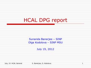
TTCrx TTCrx Clocking Changes OLD SCHEMATIC OLD SCHEMATIC Cat 5 quad cable HTR Board TTC Fanout Board SLB Board (holds 6 SLBs) TTC FPGA BC0 TTCrx TI (16) BC0 L1A TTC 1 to 8 Fanout L1A 40MHz BC0 L1A 40MHz 80 MHz LVPECL Crystal 40MHz 1 to 8 Fanout PECL 80 MHz Clock 1 2 Fanout 80 MHz system Clock/2 40 MHz clean Single width VME Cat 6/7 quad cable (allows LVDS/PECL) NEW SCHEMATIC TTC Fanout Board 80 MHz LVPECL Crystal FPGA SLB TI (16) 80MHzPECL TTC 1 to 8 Fanout QPLL SLB BC0 80MHz SLB BC0 BC0 40MHz 1 to 8 Fanout SLB SLB TTC 40 MHz system 40MHzPECL 1 to 8 Fanout SLB 40 MHz clean TTC Broadcast TTC mezz TTC broadcast bus Double width VME LVDS/PECL Depends on which input used….
New clock Scheme Cat6/7 RJ45 TTC BC0 CC40CC80 QPLL TTCrx ‘CC’ means Clean Clock TTC TTCMezz TTC broadcast, L1A, BCR, EVR, CLK40 RJ45 Xilinx CC80 CC40 SLB BC0
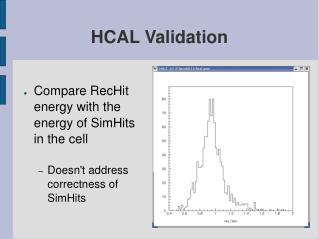
FPGA TTCrx (or daughter card) PCK953 LVPECL- to-LVTTL Fanout (top layer) PCK953 LVPECL- to-LVTTL Fanout (top layer) PECL fanout PECL fanout QPLL MC100LVEL37 80.0789 MHz 3.3V crystal Diff. PECL CK CK CK/2 CK/2 TTC daughter card IN IN_b Notes: SLBs require fanout of CLK40, BC0. FE-link possibly requires CLK80. PECL fanout was tested in TB2002. One Cat6E cable (low x-talk) replaces the 2 Cat5 cables used in TB2002. TTC and BC0 remain LVDS as in Weiming’s board. HTR needs Broadcast bus, BCntRes and L1A: from TTCrx if we get it to work, otherwise we have to fan them out. Fanout – HTR scheme TTC fiber Fanout buffer O/E TTC TTC LVDS TTC DS90LV001 Low-jitter Fanout x 15 ~Fifteen RJ45 connectors Brdcst<7:2>, BrcstStr, L1A, BCntRes to xilinx and SLBs e.g. DS90LV110 RJ45 TTC LVDS Fanout x 8 .. .. .. .. Diff. to 6 SLBs Single-end to 2 xilinx .. .. .. .. RX_BC0 LVDS Brdcst<7:2>, BrcstStr LVDS BC0 Cat6E or Cat7 cable Q1 Q2 Q3 Q4 Q5 Q6 Q7 Q8 CLK40 3.3V-PECL To 6 SLBs Diff. to 2 Xilinx + termin. CLK40 LVDS 2 Test Points for CLK40 and BC0 .. .. 8 clks to TLKs CLK80 LVDS MC100LVE310 3.3V PECL NB100LVEP221 is LVDS compatible AN1568/D Fig 11 Onsemi.com CLK80 3.3V-PECL …….. …….. 15 Cables & Connectors tbd Fanout x 15 Brdcst<7:2>, BrcstStr, BCntRes, L1A …….. …….. …….. …….. CMOS LVDS or diff PECL 15 connectors on bottom layer ? Fanout Board 8 clks to TLKs + TPs HTR 9U Front-panel space = 325 mm ; => space per connector ~ 21.5 mm Tullio Grassi <tullio@physics.umd.edu>
HCAL TriDAS Integration • First integration completed, summer 02 • FE HTR DCC SLINK CPU • All links well established • No obvious clocking problems • Work needed on synch monitoring and reporting • Improvements expected using crystal for TI refclk • Will always have TTC/QPLL clock as backup… • HTR firmware fairly mature • Switch to Virtex2 all but complete • TPG and BCID ready but not tested • To commence when next HTR version delivered and Wisconsin TPG boards delivered (est Q4 2002) • Will be main effort when next HTR version arrives Dec 2002
Integration Goals 2003 • Continued development of HTR and DCC firmware • Commission TPG path • Firmware, LUTs, synchronization, SLB output… • Monitoring, error reporting, etc. (both cards) • We need to settle on where the preliminary US-based integration will take place • We propose that this be at FNAL • Full system as in the previous testbeam • Except TPG which will be done initially at UMD • Moved to FNAL if needed • Testbeam in the summer (to begin in spring) • Same goals as summer 02 – support calibration effort and continue commissioning the system • Operate a “vertical slice” for an extended period of time, Fall 03 • Fully pipelined, monitoring, TPG, DAQ, synchronization, clocking…. • Develop software to support DAQ activities • Testbeam software improvements • Software for commissioning HTR needed • Allow us to verify fiber mapping • Download LUTs, firmware version, etc.
Overall Commissioning Schedule • Summer 2003 testbeam • Repeat previous test w/production prototype boards • Fall 2003 Slice tests • HCAL will join as schedule allows • 2003/2004 HCAL burn-in • Continue with firmware development/integration as needed • 2004/2005 Vertical Slice and magnet test • We will be ready • All HCAL TriDas production cards involved • October 05 beneficial occupancy of USC • Installation of all racks, crates, and cards • We do not anticipate any hardware integration • Should be all firmware / timing / troubleshooting
Installation Requirements • Production cards will be available, all systems • Front-end emulator will be critical • No other way to light up the fibers during installation • Design very close to actual front-end card (GOL, not TI) • Built by FNAL • Close interaction with UMD on board • UMD firmware • HCAL mapping nightmare will have to be implemented very carefully • Will need to be able to connect to rack CPU from inside shield wall as we plug the fibers in one at a time • Will need to have audio communication between operators inside shield wall and at VME racks
Installation Manpower Needs • Drawing on D Level 2 experience for the current Tevatron Run 2a… • Each significant card requires on-site expertise: • Probably 1-2 postdoc-level (or above) and 1 engineer • Maybe the same engineer for both DCC and HTR… • HCAL will have an electronics setup at CERN • Total personnel estimate: • Front End 1 • HTR 2 • DCC 2 • Miscellaneous (grad students, transients, etc.) maybe 4? • Very difficult to say with any accuracy