Download
1 / 84
890 likes | 946 Views
BME 301: Biomedical Sensors. Lecture Note 2: Sensor C haracteristics , Transducer Systems , Displacement and Temperature Sensors. Sensors. Electrical Input. Physical parameter. Electrical Output. Physical Output. Sensor is a Transducer: What is a transducer?.

E N D
BME 301: Biomedical Sensors LectureNote 2: Sensor Characteristics, TransducerSystems, DisplacementandTemperatureSensors BME 301 Lecture Note 2 - Ali Işın 2014
Sensors Electrical Input Physical parameter Electrical Output Physical Output Sensor is a Transducer:What is a transducer? A device which converts one form of energy to another e.g. Piezoelectric: Force -> voltage Voltage-> Force Actuators BME 301 Lecture Note 2 - Ali Işın 2014
Performance Characteristics 1/3 • Transfer Function: • The functional relationship between physical input signal and electrical output signal. Usually, this relationship is represented as a graph showing the relationship between the input and output signal, and the details of this relationship may constitute a complete description of the sensor characteristics. • Sensitivity: • Relationship between input physical signal and output electrical signal. • The ratio between a small change in electrical signal to a small change in physical signal. As such, it may be expressed as the derivative of the transfer function with respect to physical signal. Typical units : Volts/Kelvin. A Thermometer would have "high sensitivity" if a small temperature change resulted in a large voltage change. • Span or Dynamic Range: • The range of input physical signals which may be converted to electrical signals by the sensor. Signals outside of this range are expected to cause unacceptably large inaccuracy. This span or dynamic range is usually specified by the sensor supplier as the range over which other performance characteristics described in the data sheets are expected to apply. BME 301 Lecture Note 2 - Ali Işın 2014
Precise Accurate Performance 2/3 • Accuracy: • Generally defined as the largest expected error between actual and ideal output signals. Sometimes this is quoted as a fraction of the full scale output. For example, a thermometer might be guaranteed accurate to within 5% of FSO (Full Scale Output) • Precision: • How repeatable the sensor is. Uniformity in reproducing one result. Depends on method. Here there is no comparison to a standard, to a particular “ideal” result. • Hysteresis: • Some sensors do not return to the same output value when the input stimulus is cycled up or down. The width of the expected error in terms of the measured quantity is defined as the hysteresis. Typical units: Kelvin (for temperature sensors) or % of FSO • Nonlinearity (often called Linearity): • The maximum deviation from a linear transfer function over the specified dynamic range. There are several measures of this error. The most common compares the actual transfer function with the ‘best straight line', which lies midway between the two parallel lines which encompasses the entire transfer function over the specified dynamic range of the device. This choice of comparison method is popular because it makes most sensors look the best. BME 301 Lecture Note 2 - Ali Işın 2014
Performance Characteristics 3/3 • Noise: • All sensors produce some output noise in addition to the output signal. The noise of the sensor limits the performance of the system based on the sensor. Noise is generally distributed across the frequency spectrum. Many common noise sources produce a white noise distribution, which is to say that the spectral noise density is the same at all frequencies. Since there is an inverse relationship between the bandwidth and measurement time, it can be said that the noise decreases with the square root of the measurement time. • Resolution: • The resolution of a sensor is defined as the minimum detectable signal fluctuation. Since fluctuations are temporal phenomena, there is some relationship between the timescale for the fluctuation and the minimum detectable amplitude. Therefore, the definition of resolution must include some information about the nature of the measurement being carried out. • Bandwidth: • All sensors have finite response times to an instantaneous change in physical signal. In addition, many sensors have decay times, which would represent the time after a step change in physical signal for the sensor output to decay to its original value. The reciprocal of these times correspond to the upper and lower cutoff frequencies, respectively. The bandwidth of a sensor is the frequency range between these two frequencies. BME 301 Lecture Note 2 - Ali Işın 2014
Basic Sensors and Principles BME 301 Lecture Note 2 - Ali Işın 2014
Transducer Systems Sensors Actuators Interface Circuits Control and Processing Circuits Power Supply I/O Channel /USER BME 301 Lecture Note 2 - Ali Işın 2014
Classification of Transducers Transducers On The Basis of principle Used Active/Passive Primary/Secondary Analogue/Digital Transducers/ Inverse Transducers Transducers may be classified according to their application, method of energy conversion, nature of the output signal, and so on. Capacitive Inductive Resistive BME 301 Lecture Note 2 - Ali Işın 2014
SPECIAL REQUIREMENTS OFSENSOR IN BIOMEDICAL APPLICATIONS • Appliances for diagnosis: measuring or mapping a parameter at a given time • Monitoring devices for measuring parameters within a given period • Built-in controlling units containing not only sensors but also actuators BME 301 Lecture Note 2 - Ali Işın 2014
Passive Transducers BME 301 Lecture Note 2 - Ali Işın 2014
Active Transducers BME 301 Lecture Note 2 - Ali Işın 2014
Selecting a Transducer • What is the physical quantity to be measured? • Which transducer principle can best be used to measure this quantity? • What accuracy is required for this measurement? • Fundamental transducer parameters • Physical conditions • Environmental conditions • Compatibility of the associated equipment • Reducing the total measurement error : • Using in-place system calibration with corrections performed in the data reduction • Artificially controlling the environment to minimize possible errors BME 301 Lecture Note 2 - Ali Işın 2014
Transducer, Sensor, and Actuator • Transducer: • a device that converts energy from one form to another • Sensor: • converts a physical parameter to an electrical output (a type of transducer, e.g. a microphone) • Actuator: • converts an electrical signal to a physical output (opposite of a sensor, e.g. a speaker) BME 301 Lecture Note 2 - Ali Işın 2014
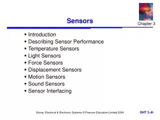
Type of Sensors • Displacement Sensors: • resistance, inductance, capacitance, piezoelectric • Temperature Sensors: • Thermistors, thermocouples • Electromagnetic radiation Sensors: • Thermal and photon detectors BME 301 Lecture Note 2 - Ali Işın 2014
Displacement Measurements • Used to measure directly and indirectly the size, shape, and position of the organs. • Displacement measurements can be made using sensors designed to exhibit a resistive, inductive, capacitive or piezoelectric change as a function of changes in position. BME 301 Lecture Note 2 - Ali Işın 2014
Resistive sensors - potentiometers Measure linear and angular position Resolution a function of the wire construction Measure velocity and acceleration From 10o to more than 50o 2 to 500mm BME 301 Lecture Note 2 - Ali Işın 2014
Resistive sensors – strain gages Devices designed to exhibit a change in resistance as a result of experiencing strain to measure displacement in the order of nanometer. For a simple wire: A change in R will result from a change in (resistively), or a change in L or A (dimension). The gage factor, G, is used to compare various strain-gage materials Is Poisson’s ratio for most metals =0.3 Semiconductor has larger G but more sensitive to temperature BME 301 Lecture Note 2 - Ali Işın 2014
Wheatstone Bridge vo is zero when the bridge is balanced- that is when If all resistor has initial value R0 then if R1 and R3 increase by R, and R2 and R4 decreases by R, then BME 301 Lecture Note 2 - Ali Işın 2014
Unbonded strain gage: With increasing pressure, the strain on gage pair BandCis increased, while that on gage pairAandDis decreased. Initially before any pressure R1 = R4 and R3 = R2 Wheatstone Bridge B A D C Fig. 2.2 legend: R1 = A, R2 = B, R3 = D, R4 = C BME 301 Lecture Note 2 - Ali Işın 2014
Bonded strain gage: - Metallic wire, etched foil, vacuum-deposited film or semiconductor is cemented to the strained surface Rugged, cheap, low mass, available in many configurations and sizes To offset temperature use dummy gage wire that is exposed to temperature but not to strain BME 301 Lecture Note 2 - Ali Işın 2014
Bonded strain gage terminology: Carrier (substrate + cover) BME 301 Lecture Note 2 - Ali Işın 2014
Semiconductor Integrated Strain Gages Pressure strain gages sensor with high sensitivity Integrated cantilever-beam force sensor BME 301 Lecture Note 2 - Ali Işın 2014
4 cm Clear plastic Saline Flush valve To patient IV tubing Gel Silicon chip Electrical cable Isolation in a disposable blood-pressure sensor. Disposable blood pressure sensors are made of clear plastic so air bubbles are easily seen. Saline flows from an intravenous (IV) bag through the clear IV tubing and the sensor to the patient. This flushes blood out of the tip of the indwelling catheter to prevent clotting. A lever can open or close the flush valve. The silicon chip has a silicon diaphragm with a four-resistor Wheatstone bridge diffused into it. Its electrical connections are protected from the saline by a compliant silicone elastomer gel, which also provides electrical isolation. This prevents electric shock from the sensor to the patient and prevents destructive currents during defibrillation from the patient to the silicon chip. BME 301 Lecture Note 2 - Ali Işın 2014
Elastic-Resistance Strain Gages Extensively used in Cardiovascular and respiratory dimensional and volume determinations. As the tube stretches, the diameter decreases and the length increases, causing the resistance to increase b) venous-occlusion plethysmography c) arterial-pulse plethysmography Filled with a conductive fluid (mercury, conductive paste, electrolyte solution. Resistance = 0.02 - 2 /cm, linear within 1% for 10% of maximal extension BME 301 Lecture Note 2 - Ali Işın 2014
Inductive Sensors Ampere’s Law: flow of electric current will create a magnetic field Faraday’s Law: a magnetic field passing through an electric circuit will create a voltage i + + + v2 v1 v - - - N2 N1 BME 301 Lecture Note 2 - Ali Işın 2014
Inductive Sensors Ampere’s Law: flow of electric current will create a magnetic field Faraday’s Law: a magnetic field passing through an electric circuit will create a voltage Self-inductance Mutual inductance Differential transformer n = number of turns of coil G = geometric form factor m = effective magnetic permeability of the medium BME 301 Lecture Note 2 - Ali Işın 2014
+ - + - LVDT : Linear variable differential transformer - full-scale displacement of 0.1 to 250 mm - 0.5-2 mV for a displacement of 0.01mm - sensitivity is much higher than that for strain gages Disadvantage requires more complex signal processing + _ (a) As x moves through the null position, the phase changes 180, while the magnitude of vo is proportional to the magnitude of x. (b) An ordinary rectifier-demodulator cannot distinguish between (a) and (b), so a phase-sensitive demodulator is required. BME 301 Lecture Note 2 - Ali Işın 2014
Capacitive Sensors Capacitive sensors For a parallel plate capacitor: 0 = dielectric constant of free space r = relative dielectric constant of the insulator A = area of each plate x = distance between plates Change output by changing r (substance flowing between plates), A (slide plates relative to each other), or x. BME 301 Lecture Note 2 - Ali Işın 2014
Sensitivity of capacitor sensor, K Sensitivity increases with increasing plate size and decreasing distance When the capacitor is stationary xo the voltage v1=E. A change in position x = x1 -xo produces a voltage vo = v1 – E. i + + Characteristics of capacitive sensors: High resolution (<0.1 nm) Dynamic ranges up to 300 µm (reduced accuracy at higher displacements) High long term stability (<0.1 nm / 3 hours) Bandwidth: 20 to 3 kHz BME 301 Lecture Note 2 - Ali Işın 2014
Example 2.1 For a 1 cm2 capacitance sensor, R is 100 MΩ. Calculate x, the plate spacing required to pass sound frequencies above 20 Hz. Answer: From the corner frequency, C =1/2πfR=1/(2π20×108)= 80 pF. x can be calculated as follows: BME 301 Lecture Note 2 - Ali Işın 2014
Piezoelectric Sensors • Measure physiological displacement and record heart sounds • Certain materials generate a voltage when subjected to a mechanical strain, or undergo a change in physical dimensions under an applied voltage. • Uses of Piezoelectric • External (body surface) and internal (intracardiac) phonocardiography • Detection of Korotkoff sounds in blood-pressure measurements • Measurements of physiological accelerations • Provide an estimate of energy expenditure by measuring acceleration due to human movement. BME 301 Lecture Note 2 - Ali Işın 2014
Vo (typically pC/N, a material property) k for Quartz = 2.3 pC/N k for barium titanate = 140 pC/N To find Vo, assume system acts like a capacitor (with infinite leak resistance): Capacitor: For piezoelectric sensor of 1-cm2 area and 1-mm thickness with an applied force due to a 10-g weight, the output voltage v is 0.23 mV for quartz crystal 14 mV for barium titanate crystal. BME 301 Lecture Note 2 - Ali Işın 2014
Models of Piezoelectric Sensors Piezoelectric polymeric films, such as polyvinylidence fluoride (PVDF). Used for uneven surface and for microphone and loudspeakers. BME 301 Lecture Note 2 - Ali Işın 2014
Transfer Function of Piezoelectric Sensors View piezoelectric crystal as a charge generator: Rs: sensor leakage resistance Cs: sensor capacitance Cc: cable capacitance Ca: amplifier input capacitance Ra: amplifier input resistance Ra BME 301 Lecture Note 2 - Ali Işın 2014
Transfer Function of Piezoelectric Sensors Convert charge generator to current generator: Ra Current Ra Ks = K/C, sensitivity, V/m = RC, time constant BME 301 Lecture Note 2 - Ali Işın 2014
Voltage-output response of a piezoelectric sensor to a step displacement x. Decay due to the finite internal resistance of the PZT The decay and undershoot can be minimized by increasing the time constant =RC. BME 301 Lecture Note 2 - Ali Işın 2014
Example 2.2 A piezoelectric sensor has C = 500 pF. Sensor leakage resistanse is 10 GΩ. The amplifier input impedance is 5 MΩ. What is the low corner frequency? BME 301 Lecture Note 2 - Ali Işın 2014
Example 2.2 C = 500 pF Rleak= 10 G Ra = 5 M What is fc,low ? Current If input impedance is increased 100 times: (Ra = 500 M ) Then the fc,low : BME 301 Lecture Note 2 - Ali Işın 2014
High Frequency Equivalent Circuit Rs BME 301 Lecture Note 2 - Ali Işın 2014
Temperature Measurement • The human body temperature is a good indicator of the health and physiological performance of different parts of the human body. • Temperature indicates: • Shock by measuring the big-toe temperature • Infection by measuring skin temperature • Arthritis by measuring temperature at the joint • Body temperature during surgery • Infant body temperature inside incubators • Temperature sensors type • Thermocouples • Thermistors • Radiation and fiber-optic detectors • p-n junction semiconductor (2 mV/oC) BME 301 Lecture Note 2 - Ali Işın 2014
A T2 T1 T1 B B E = f(T1 –T2) Thermocouple • Electromotive force (emf) exists across a junction of two dissimilar metals. Two independent effects cause this phenomena: 1- Contact of two unlike metals and the junction temperature (Peltier) 2- Temperature gradients along each single conductor (Lord Kelvin) E = f (T12 - T22) • Advantages of Thermocouple • fast response (=1ms), small size (12 μm diameter), ease of fabrication and long-term stability • Disadvantages • Small output voltage, low sensitivity, need for a reference temperature BME 301 Lecture Note 2 - Ali Işın 2014
A T1 T2 T1 B B E = f(T1 –T2) Thermocouple • Empirical calibration data are usually curve-fitted with a power series expansion that yield the Seebeck voltage. T: Temperature in Celsius Reference junction is at 0 oC BME 301 Lecture Note 2 - Ali Işın 2014
Thermocouple Laws 1- Homogeneous Circuit law: A circuit composed of a single homogeneous metal, one cannot maintain an electric current by the application of heat alone. See Fig. 2.12b (next slide) 2- Intermediate Metal Law: The net emf in a circuit consisting of an interconnection of a number of unlike metals, maintained at the same temperature, is zero. See Fig. 2.12c (next slide) • Second law makes it possible for lead wire connections 3- Successive or Intermediate Temperatures Law: See Fig. 2.12d (next slide) • The third law makes it possible for calibration curves derived for a given reference-junction temperature to be used to determine the calibration curves for another reference temperature. T3 T1 T2 BME 301 Lecture Note 2 - Ali Işın 2014
A T2 T1 B E = f(T1 –T2) Thermoelectric Sensitivity • For small changes in temperature: • Differentiate above equation to find , the Seebeck coefficient, or thermoelectric sensitivity. Generally in the range of 6.5 - 80 V/oC at 20 oC. BME 301 Lecture Note 2 - Ali Işın 2014
Thermistors • Thermistors are semiconductors made of ceramic materials whose resistance decreases as temperature increases. • Advantages • Small in size (0.5 mm in diameter) • Large sensitivity to temperature changes (-3 to -5% /oC) • Blood velocity • Temperature differences in the same organ • Excellent long-term stability characteristics (R=0.2% /year) • Disadvantages • Nonlinear • Self heating • Limited range BME 301 Lecture Note 2 - Ali Işın 2014
R3 R1 V vb va R2 Rt Circuit Connections of Thermistors • Bridge Connection to measure voltage • Amplifier Connection to measure currents BME 301 Lecture Note 2 - Ali Işın 2014