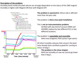
Download

1 / 31
310 likes | 417 Views
Updated Description of the Proposed OXCs. ICCS - Univ. of Peloponnese. Once more, the architectures…. Two architecture families based on the Broadcast-n-Select.

E N D
Updated Description of the Proposed OXCs ICCS - Univ. of Peloponnese
Once more, the architectures… Two architecture families based on the Broadcast-n-Select. The evolution from Class-0 to Class- III allows for different functionality. Performance assessment is mandatory to understand the implications of a step-by-step process. Scalability v. Cascadeability considerations due to ASE. Each node can be constructed using two technologies: O-O-O and O-E-O NOBEL, WP6 Munich meeting – ICCS/UoPelop
Objective Overview Migration period from static to dynamic and from circuits to packets From low/medium to high capacity Physical layer modeling From current technologies to future ones They operate in both O-E-O and O-O-O mode Some better in O-E-O than O-O-O NOBEL, WP6 Munich meeting – ICCS/UoPelop
Proposed Migration Phases SONET/SDH and Electronic Switches/Routers Aggregation/Grooming cards and Optical Switch Matrix (signaling circuitry). Non-Transparent solution 3R/buffering (!!), no processing and Optical Switch Matrix and WRN. O-E-O Service Transparent solution Higher functionality in the Optical Layer (O-E-O or O-O-O) NOBEL, WP6 Munich meeting – ICCS/UoPelop
O-E-O Transparent v. Non-Transparent The switching matrix is all-optical O-E-O and even buffers can be introduced without compromising “service transparency” Could be an important intermediate step! True transparent networks (physical layer) is an absurdity. NOBEL, WP6 Munich meeting – ICCS/UoPelop
Class-0 N:1 1:N NOBEL, WP6 Munich meeting – ICCS/UoPelop
l1 lM N:1 1:N Line Card Line Card Line Card Line Card Burst Card Burst Card Burst Card Burst Card l1 lM Non-Transparent O/E Solution NOBEL, WP6 Munich meeting – ICCS/UoPelop
N:1 1:N λ1 Bit-Synchronisation and buffering card Bit-Synchronisation and buffering card λΜ Transparent O/E Solution λ1 Bit-Synchronisation and buffering card Bit-Synchronisation and buffering card λΜ NOBEL, WP6 Munich meeting – ICCS/UoPelop
M xK router N:1 1:N M xK router K:1 M xK router Class-I NOBEL, WP6 Munich meeting – ICCS/UoPelop
M x M router M xK router N:1 1:N M xK router M x M router K:1 M xK router M x M router Class-II l-S-l NOBEL, WP6 Munich meeting – ICCS/UoPelop
M x M router NxM router M xK router 1:N M x M router NxM router M xK router K:1 NxM router M x M router M xK router Class-IIB NOBEL, WP6 Munich meeting – ICCS/UoPelop
Class-III S-l-S NOBEL, WP6 Munich meeting – ICCS/UoPelop
Class-IV Very simple architecture A single active element is needed to perform the switching function a tunable wavelength converter (all-optical) fixed receiver/tunable transmitter (o/e) The o/e solution could of importance bit-rate transparent the industry to concentrate efforts in optimizing a single element (transceiver) integrates “switching” and “transmission” NOBEL, WP6 Munich meeting – ICCS/UoPelop
Class-IV NOBEL, WP6 Munich meeting – ICCS/UoPelop
N:1 1:N Architecture-I NOBEL, WP6 Munich meeting – ICCS/UoPelop
Class-0 is well established now! http://www.metconnex.com http://www.capellaphotonics.com http://www.avanex.com/ http://www.jdsu.com http://www.coadna.com http://www.xtellus.com No comprehensive studies so far dealing with the evolution of this architecture with technology NOBEL, WP6 Munich meeting – ICCS/UoPelop
Three options for Class-0 Switching element, passive component (MEMS) Switching element, active component (SOA) Switching elements with the Potential to Affect Transmission Properties NOBEL, WP6 Munich meeting – ICCS/UoPelop
Multifunctional variation of Class-0 • Tunable dispersion control element as shutter • Can be used to match the dispersion of channels from different paths • Can improve the physical layer performance of each path by tweaking the dispersion • Reduced nonlinear effects NOBEL, WP6 Munich meeting – ICCS/UoPelop
Possible Shutters • MEMS • Fiber Bragg Grating • Two examples given for illustration • FBG with dual heaters • FBG with third order chirp • Long Period Grating NOBEL, WP6 Munich meeting – ICCS/UoPelop
Shutter Shutter Shutter Shutter Shutter Shutter Shutter Shutter N:1 1:N TFBG Shutter Shutter Shutter Shutter Shutter Shutter Shutter Shutter Shutter Shutter NOBEL, WP6 Munich meeting – ICCS/UoPelop
λ1 FBG with dual heatersJ.A. Rogers et.al. OPTICS LETERS 24(19) 1999 pp. 1328-1330 D1< D2 <D3 Heaters off Time delay combined effect NOBEL, WP6 Munich meeting – ICCS/UoPelop
FBG with third order chirpY.W. Song et.al. JLT 20 (12) 2002 pp. 2259-2266 NOBEL, WP6 Munich meeting – ICCS/UoPelop
Case Study • Two systems are investigated with different characteristics • Both have 160 km node distance. Both have TDC at the node as a switching element • Modelled as ideal component for the time being • Different span dispersion compensation schemes: • No compensation • Partial compensation • Different total length and Tx power. Into account, ASE, SPM, XPM, FWM NOBEL, WP6 Munich meeting – ICCS/UoPelop
First system modelled as TDC TDC 4 4 Span Span s s OXC OXC Tx Tx Rx Rx TDC TDC SMF SMF 40 km 40 km EDFA EDFA • 40 km spans. Node every 4 spans (160 km) • 960 km (24 spans 6 nodes) • No DCF at each span. TDC at node and at receiver • 32 Channel • 10 Gbit/sec • NRZ modulation • 50 GHz spacing • 2 mW Tx power NOBEL, WP6 Munich meeting – ICCS/UoPelop
Q-factor map NOBEL, WP6 Munich meeting – ICCS/UoPelop
First system comments • Optimum compensation scheme: • 90-95% (2450-2580 ps/nm) of span dispersion at the node; not necessarily all at the TDC • 40-70% (330-1140 ps/nm) of residual dispersion at the Rx • Away from this area steep Q factor degradation • quickly reaches areas with unacceptable performance • even with several effects omitted • Tuning appropriately the dispersion at each node can result in a feasible and cost effective system. NOBEL, WP6 Munich meeting – ICCS/UoPelop
80 km spans. Node every 2 spans (160 km) 1280 km (16 spans 8 nodes) some DCF at each span. TDC at node only 32 Channel 10 Gbit/sec NRZ modulation 50 GHz spacing 5 mW Tx power DC TDC TDC TDC TDC TDC Second system modelled as 2 2 Span Span s s OXC OXC Rx Tx Tx SMF SMF DCF DCF 80 km 80 km EDFA EDFA NOBEL, WP6 Munich meeting – ICCS/UoPelop
Q-factor map NOBEL, WP6 Munich meeting – ICCS/UoPelop
Dispersion map NOBEL, WP6 Munich meeting – ICCS/UoPelop
Optimum compensation scheme 70-80% (950-1080 ps/nm) of the span dispersion with a DCF section around 90% (490-730 ps/nm) of the residual dispersion of the two sections at the OXC results in acceptable value of the Q factor Taking into account the margin needed for the omitted effects The dispersion map shows the following case: 75% (1020 ps/nm) per span compensation 90% (610 ps/nm) of the residual dispersion of the two spans compensated at the OXC Second system comments NOBEL, WP6 Munich meeting – ICCS/UoPelop
In principle similar results can be achieved by static broadband compensation at the OXC using either fixed length of DCF or broadband compensator In practice this is not feasible since channels added to the link from different paths require individual levels of compensation different operational conditions different path lengths Per channel compensation is required General comment NOBEL, WP6 Munich meeting – ICCS/UoPelop