Download
1 / 24
250 likes | 418 Views
Digital Filtering Performance in the ATLAS Level-1 Calorimeter Trigger. David Hadley on behalf of the ATLAS Collaboration. Outline. ATLAS Trigger and L1Calo Architecture Digital Filter Implementation Digital Filter Performance. ATLAS Trigger and L1Calo Architecture . ATLAS Trigger.

E N D
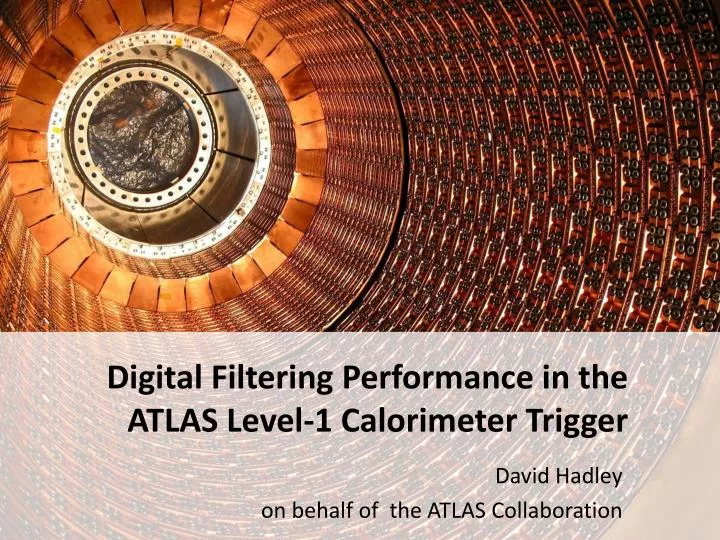
Digital Filtering Performance in the ATLAS Level-1 Calorimeter Trigger David Hadley on behalf of the ATLAS Collaboration
Outline ATLAS Trigger and L1Calo ArchitectureDigital Filter ImplementationDigital Filter Performance
ATLAS Trigger • ATLAS three level trigger: • Level 1 : hardware-based, pipelined with a fixed latency <2.5μs, maximum 75kHz accept rate. • Level 2 : software-based, seeded by L1 identified Regions of Interest. ~40ms mean processing time, accept rate ~2kHz. • Event Filter : software-based, full detector information is used. ~4s mean processing time. Accept rate ~200Hz. • Data are buffered at 40MHz LHC bunch-crossing rate and stored on-detector for 2.5μs awaiting Level-1 accept. • Level-1 has three subsystems: • Calorimeter Trigger (L1Calo). • Muon Trigger • Central Trigger Processor. • see related talk by Johan Lundberg. Digital Filter Performance - David Hadley - RT2010
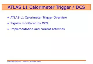
L1Calo Architecture • Fixed Latency <2.5μs. • Massively parallel. • Heavily FPGA based. Analogue Calorimeter signals (7168) 8-bit trigger towers 9-bit jet elements (2x2 trigger towers) Digital Filter Performance - David Hadley - RT2010
L1Calo Trigger • ATLAS sampling calorimeters use two distinct technologies: • Liquid Argon ionisation calorimeter used in EM layer and high ηhadronic layer. • Scintillating tile readout with PMTs are used in the hadronic layer η<1.5. • Analogue signals from calorimeter cells are summed into 7168 approximately projective trigger towers of ηxφ~0.1x0.1. • Trigger algorithms operate on reduced granularity information. LAr Tiles (semi-projective segmentation ) Digital Filter Performance - David Hadley - RT2010
L1Calo Trigger • “Sliding-window” algorithms search for high-ET objects. • In reality windows are processed in parallel. • For example: Jet and energy-sum ECAL+HCAL • Operates on jet elements 2x2 towers. • Energy in window (EM+Had) > threshold. • Variable window size up to 4x4. • Same module does total-ET and missing-ET triggers. Digital Filter Performance - David Hadley - RT2010
A 7TeV Event Trigger By L1Calo Digital Filter Performance - David Hadley - RT2010
Pre-Processor Digital Filter Implementation Digital Filter Performance - David Hadley - RT2010
Digital Filter • Trigger tower pulses are several bunch crossings wide. • Need to associate trigger tower pulses with a single bunch crossing. • A 5-sample digital Finite Impulse Response (FIR) filter is applied. • Filter has 5 coefficients with limited 4-bit precision. • Filter output: • Improved energy measurement. • Minimised effects of noise. • Improved bunch-crossing identification. Digital Filter Performance - David Hadley - RT2010
Choosing the Filter Coefficients • For white Gaussian noise, the optimum choice of filter coefficients is matched to the pulse shape. • Coefficients are proportional to the signal pulse height at each sample. • Pulse shapes vary throughout the detector and each trigger tower could have its own set of filter coefficients. • 7,168 towers with 5 coefficients = 35,840 free parameters! Digital Filter Performance - David Hadley - RT2010
Choosing the Filter Coefficients • Compare the performance of the following three sets of filters, where a=filter coefficients. • Matched Filter – each tower has a filter individually-matched to its pulse shape. • Common Filter – a single filter is applied to all towers in a calorimeter layer. Three sets are used: • Filters were chosen which match shapes of towers with median width. • Pass-through Filter – input and output are identical. Digital Filter Performance - David Hadley - RT2010
Digital Filter Performance Digital Filter Performance - David Hadley - RT2010
Simulating the Performance • The digital filter performance can be accurately simulated: • Measure the pulse shape from calibration pulses (approximately the same shape as physics pulses). • Scale the shape to produce pulses of chosen energies. • Add the simulated pulse to empty events (selected with a random trigger) containing only detector noise. Calibration pulse Real detector noise Digital Filter Performance - David Hadley - RT2010
Bunch-crossing ID efficiency • 1-3 GeV before reach full efficiency, depending on filter. • Slower turn-on curve for Pass-through. • Comparable performance for Matched and Common. • Fit to extract σ of curve: Digital Filter Performance - David Hadley - RT2010
Noise Rejection • Noise PDF for a single tower (left). • The total probability of noise output > 0.5GeV for all towers in the LAr EM Barrel (right). • Improved noise rejection with a matched/common filter but little difference between them. Digital Filter Performance - David Hadley - RT2010
Energy Resolution from Detector Noise • Energy residual (measured-simulated) for a 25GeV pulse (left). • Gaussian width of energy residual is plotted for all towers in the LAr EM barrel (right). • Again, little difference between Matched and Common. • Clear improvement over Pass-through. Digital Filter Performance - David Hadley - RT2010
Optimising Usage of the Look-up Table Range • Using a peak coefficient of 15 gives the best precision for matching the filter to the pulse shape. • Precisely matching to individual towers pulse shape does not significantly improve performance. • We can change the peak coefficient to optimise the usage of the look-up table (LUT) range. Digital Filter Performance - David Hadley - RT2010
Choice of Filter Coefficients for Early LHC Running • Based on these studies the strategy decided for 2009-2010 running: • Common filter applied across entire calorimeter layer, matched to the average pulse shape in that layer. • Coefficients scaled to optimise usage of the LUT range. Digital Filter Performance - David Hadley - RT2010
Look-up Table ET Calibration • Analogue gains are applied to scale the input pulses to 4 ADC per GeV. • LUT table applies pedestal subtraction, noise cuts and final ET calibration. • At present, only scale filter output back to the input scale. • Initial calibration of the LUT slopes were based on calibration pulses. • Preliminary checks of correlation show calibration is working well for collisions. • Nominal 4 ADC input to 1 LUT output, expect a gradient ¼. Digital Filter Performance - David Hadley - RT2010
Summary • L1Calo Pre-processor digital filter shows good performance in selecting the correct bunch-crossing, rejecting noise, and improving energy resolution. • The Common digital filter configuration was implemented for 2009-2010 running. • Initial cross checks of LUT calibration with collision data are encouraging. • The process of understanding and optimising the trigger with collisions is continuing. • We are looking forward to new physics events identified with L1Calo! Digital Filter Performance - David Hadley - RT2010
Backup Slides Digital Filter Performance - David Hadley - RT2010
Performance with Different Peak Coefficients • BCID efficiency: • Energy resolution: • Noise probability:
L1Calo Trigger (in full) • e/gamma and τ/hadron • “Sliding-window” algorithms search for high-ET objects. • In reality windows are processed in parallel. Jet and energy-sum ECAL+HCAL • Operates on jet elements 2x2 towers. • Energy in window (EM+Had) > threshold. • Variable window size. • Same module does total-ET and missing-ET triggers. • Central cluster > threshold. • Hadronic and e.m. isolation requirements in surrounding towers. • Double counting is avoided by requiring a local ET maximum. Digital Filter Performance - David Hadley - RT2010