Download
1 / 32
320 likes | 455 Views
CMS Level-1 Upgrade Calorimeter Trigger Prototype Development. P. Klabbers 1 , M, Bachtis 1 , J. Brooke 2 , M. Cepeda Hermida 1 , K. Compton 3 ,

E N D
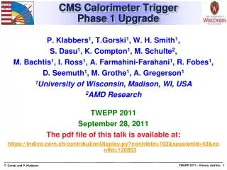
CMS Level-1 Upgrade Calorimeter Trigger Prototype Development • P. Klabbers1, M, Bachtis1, J. Brooke2, M. Cepeda Hermida1, K. Compton3, • S. Dasu1, A. Farmahni-Farahani3, S. Fayer4, R. Fobes1, R. Frazier2, C, Ghabrous, T. Gorski1, A. Gregerson3, G. Hall4, C. Hunt4, G. Iles4, J. Jones6, C. Lucas2, • R. Lucas4, M. Magrans5, D. Newbold2,7, I. Ojalvo1, A. Perugupalli1, M. Pioppi4, • Rose4, I. Ross1, D. Sankey7, M, Schulte3, D. Seemuth3, W.H. Smith1, • J. Tikalsky1, A. Tapper4, T. Williams2 • 1Physics Department, University of Wisconsin, Madison, WI, USA • 2University of Bristol, Bristol, UK • 3Engineering Department, University of Wisconsin, Madison, WI, USA • 4Imperial College, London, UK • 5CERN, Geneva, Switzerland • 6Iceberg Technology, UK • 7Rutherford Appleton Laboratory, UK • TWEPP 2012 - September 18, 2012 • The pdf file of this talk is available at: • https://indico.cern.ch/contributionDisplay.py?contribId=86&sessionId=51&confId=170595
Present CMS Level-1 andCalorimeter Trigger • Only calorimeter and muon systems participate 3<||<5 ||<3 ||<3 ||<1.6 0.9<||<2.4 ||<1.2 4K 1.2 Gbaud serial links Cu cables e/, jets, ET, HT, jet counts muons • Regional and Global Calorimeter Trigger (RCT and GCT) • Pipelined system receives Trigger Primitives (TPs) from 8000 ECAL/HCAL/HF towers • Finds 8 e/g candidates, creates 14 central tower sums, 28 quality bits, and forwards 8 HF towers and 8 HF quality bits
CMS Calorimeter Geometry EB, EE, HB, HE map to 18 RCT crates Provide e/g and jet, t, ET triggers
Present Calorimeter Algorithms • Jet or t ET • 12x12 trig. tower ET sliding in 4x4 steps w/central 4x4 ET > others & > threshold • t: isolated narrow energy deposits • Energy spread outside t veto pattern sets veto • t Jetif all 9 4x4 region t vetoes off • e/g Rank = Hit+Max Adjacent Tower • Hit: H/E < Small Fraction • Hit: 2 of 5-crystal strips >90% ET in 5x5 Tower (Fine Grain) • Isolated e/g (3x3 Tower) • Quiet neighbors: all 8 towerspass Fine Grain & H/E • One of 4 corners 5 EM ET < Thr.
Collisions at the LHC • LHC currently delivering starting luminosities up to 7.5×1033/cm2s with 50ns bunch spacing at CMS and ATLAS • Level-1 Trigger rates of 90 kHz • Avg. number of interactions per crossing (pileup) ~30-35 to start • LHC luminosity could increase up to 2×1034/cm2s by the end of 2017 (start of LHC long shutdown 2) • 25 ns bunch spacing is the plan • 50 ns may be easier and more reliable for the LHC • Estimated average pileup from ~50 to >100 events per collision • At CMS – Trigger and Detector Upgrades are essential to ensuring continued physics performance • Keep thresholds as low as possible • Reduce the effects of pileup • Trigger can improve algorithms and resolution
Planned Improvements to Calorimeter Algorithms • Electron/photon • Use Hadronic Calorimeter depth segmentation • ½ tower resolution • Flexible isolation criteria, separate HCAL and ECAL • Jet • Improve resolution from 4 tower to 1 tower • Use full Forward Calorimeter Granularity • Flexible jet diameter 8-12 towers, circular or square • Different algorithm options at the same time • Tau • Use smaller clusters, not 12x12 tower jets • More candidates of each type • Currently limited to 8 e/g of 2 types, 12 jets of 3 types (Central, Tau, Forward) • Pileup Subtraction • Move High-Level trigger PU corrections to Level-1 • MET, HT, MHT Calculation • Calculate ET Sums, Missing ET from clusters These all will improve resolution, rates, and efficiencies!
CMS Calorimeter Upgrade Level-1 Trigger Architecture Configurations Time Multiplexed Calorimeter Trigger Fully Pipelined Calorimeter Trigger Layer 1 Layer 2 Demux
Layers of the Calorimeter Trigger • Layer 1 • Reception of Trigger Primitives • Option 1: Formation of trigger tower clusters and characterization bits • Option 2: Multiplexing time slices of Trigger Primitives • The filling • Optical fibers • Layer 2 • Formation of Trigger Objects • Pipelined – multiple processors and data sharing • Time Multiplexed – processor/time slice, all algorithms in one processor
VadaTech V894 Crate • Enhancement to “CMS Standard” VT892 Crate • Supports 12 Double-Width, Full Height AMC Cards with redundant Power Supply and MCH Slots • MCH1—commercial MCH module, used for GbE connectivity and IPMI control (part of AMC spec) • MCH2—contains Boston University module, “AMC13”, for TTC downlink and crate DAQ interface • Each AMC Slot Contains backplane 20 ports with a Tx & Rx pair • Ports 0-3—for GbE, TTC, DAQ • Ports 4-7—star fabric to slot MCH1 • Ports 8-11—star fabric to slot MCH2 • Port 12-15 and 17-20—not connected on VT892, but enhanced with custom fabric on VT894 • A VT894 is otherwise identical to a VT892 with the addition of connections to otherwise unconnected ports 6 10 2 4 8 12 1 * 11 3 5 9 7 *See backup slides for details
Wisconsin Calorimeter Trigger Processor (CTP)Virtex-6 Prototype Board MMC Circuitry Power Supplies JTAG/USB Console Interface Mezzanine Front End FPGA XC6VHX250T Back End FPGA XC6VHX250T 4X Avago AFBR-820B Rx Module Dual SDRAM for dedicated DAQ and TCP/IP buffering Avago AFBR-810B Tx Module
CTP-6 Features • Dual Virtex-6 FPGAs (Front-End/Back-End), VHX250T or VHX380T with 6.5 Gbps-capable links • Design optimized for the Compact Trigger Architecture • FE FPGA has 48 Rx optical input links • 24 intra-board links to forward data from the Front-End to Back-End FPGA • 12 Backplane links (FE Tx, BE Rx) • 12 Frontpanel Optical Outputs (from either FE or BE FPGA on per link basis) • Supports TCP/IP for GbE connection • Dedicated 25A power module for each FPGA logic core
CTP-6 Testing • 2 CTP-6s Built • Extensive loopback testing on the 12x outputs to the 48x inputs @ 6.4 Gbps over 5m cables • Link drvr/rcvr settings affect results • Have settings for error-free operation (see 98 hour test) • Error free operation on the intra-card FE-to-BE links at 6.4 Gbps • Currently surveying backplane links by moving CTP cards between different slots • In process of firmware refit to make this more efficient • About 25% of VT894 custom fabric links tested • run @ 4.8 Gbps for ~30 min without errors
V894 Crate Test Setup TTC Downlink BU AMC13 UW CTP-6 UW CTP-6 UW Aux Vadatech MCH
CTP-6 6.4 Gbps 98-hour Loopback • 12x Loopback from BE FPGA to FE FPGA using 5m OM-3 cable • 320MHz link clock derived from AMC13 40MHz • Scope view at FE FPGA Rx pins • Zero Bit Errors in the interval on all 12 fibers • Pre/De-emphasis & equalization settings at Tx & Rx ports affect results
CTP-6 Summary • New system of prototype hardware developed, including the CTP-6 and VadaTech 894 Backplane • Not shown: Custom 25A power modules, Crosspoint I/O cards for data sharing currently being built • Tests going well • Validating the design formula • Mechanical, Power, Balanced I/O • Dedicated loopback tests with CTP-6 • Surveying the VT894 backplane links • A lot more to do • Future designs in the pipeline • CTP-7 as Xilinx 7-series products continue to become more readily available
The MP7 Summary • Virtex 7 based processing card • Essentially large FPGA with a lot of I/O • 1.0 - 1.4 Tb/s of optical I/O • 48-72 Tx & 48-72 Rx @ 10G • 50 Gb/s of electrical I/O • 28 LVDS @ 1.8 Gb/s • Dual 72Mb or 144Mb QDR RAM • Clocked 500MHz • Extensive monitoring • 15 voltage & current sensors • 16 temperature sensors • Firmware storage via MicroSD card or standard PROM • MicroSD card allows fast storage of many firmware versions • USB2 Console via microcontroller
Test Status • JTAG access to FPGA & microcontroller via Complex Programmable Logic Device (CPLD) verified • QDR RAM functionality tested to 375Mhz • 2x 13.5 Gb/s on each port • Need to try @ 500MHz • MMC code ported to MP7 from previous Mini-T* • More monitoring than ever before • All power supplies V/I/P, humidity, temperature, etc. • IPbus** is stress tested • 10 million packets, and no packets have been dropped. *See talk during TWEPP2011 **More details in this talk
Link Testing…. 240Gb/s (24 x10Gb/s) Rx Tx Tx Rx
Tx & Rx of 1 Tb/s • Simultaneous 48 channel 8B/10B encoding test • Transmitted 7x1013 bits per channel without any bit or alignment errors (includes data capture, counter and synchronisation). • Simultaneous 24 channel PRBS31 (harsher) test with Xilinx IBERT • Limited to ½ the channel due to IBERT software limitations • Still valid because links split into 2 columns on each side of the die • Transmitted 1013 bits per channel without any errors • Neither test had any special tuning (e.g. pre-emphasis)
PRBS7 – Full Column (24 Chan) Preliminary SerDes results • Clean optical eye (left) and electrical received eye (right). • Still have to enable pre-emphasis in the optical receiver • Should improve the rise time of the eye • PCB manufacturing improvements are possible if needed.
Summary MP7 • Card passes all basic tests • JTAG chain based on CPLD OK • FPGA OK • All 48 Tx & 48 Rx channels running at 10G • Transmitted ~ exabit during testing (1018) without error • QDR RAM operating (not yet tested at 500MHz) • Microcontroller programmed and performing MMC duties • Satisfied with card performance • Will evaluate 144 link (rather than 92) @ 10G in November when the XC7VX690T becomes available.
IPbus / μHAL • The CMS experiment’s new hardware control “standard” • Version 1.0 released in August 2012 • Used by a growing number of other experiments also • Hardware control via gigabit Ethernet • UDP as the transport protocol (software support for TCP available) • Complete solution is provided: • IPbus/UDP Firmware module to add into your FPGA design • µHAL application programming library • ControlHub for serialising concurrent accesses from multiple clients • Downloads + documentation: https://svnweb.cern.ch/trac/cactus TWEPP 2012 -- IPbus / μHAL, P Klabbers, U. Wisconsin
IPbus / μHAL use-cases • IPbus is based on well-established networking technology • Thus very flexible, with usage easily ranging from: A single board on a bench... ...to something much bigger: IPbus Firmware footprint is small Real-world resource usage in a low-end Xilinx Spartan 6 (XC6LX16-CS324) FPGA TWEPP 2012 -- IPbus / μHAL , P. Klabbers, U. Wisconsin
IPbus / μHAL Performance • Performance is dominated by latency. • Current firmware only supports single UDP packet in flight per target device. • To minimise network transports, requests are queued and only despatched when necessary. 3 UDP packets required 2 UDP packets required • The next release of IPbus aims to improve performance figures further by: • Reducing firmware latency. • Support for multiple packets in flight. • This should be available in early 2013. TWEPP 2012 -- IPbus / μHAL, P. Klabbers, U. Wisconsin
Summary • Two FPGA-based high speed calorimeter trigger processing boards, and a new mTCA backplane built this year • CTP-6 and VT894 • Inter-crate sharing card, Crosspoint I/O being built • MP7 • Intense testing underway for both cards, backplane • IPbus/mHAL tool available and in use • These will make possible a CMS Level-1 calorimeter trigger upgrade for the LHC luminosity increases • More sophisticated algorithms, resolution possible • Can keep thresholds as low as possible to preserve physics • Modularity will allow staging of new system to have slice ready by the end of LHC long shutdown 1 (end of 2014) and deploy the system in parallel • Keep up with changing LHC conditions
CMS Trigger & DAQ Systems • Level-1 Trigger • LHC beam crossing rate is 40 MHz & at full Luminosity of 1034 cm-2s-1109 collisions/s • Reduce to 100 kHz output to High Level Trigger and keep high-PT physics • Pipelined at 40 MHz for dead time free operation • Latency of only 3.2 msec for collection, decision, propagation Level-1 Detector Front-ends Trigger Readout Event Controls Switch Fabric Manager Farms Computing Services
V894 Custom Fabric by AMC Slot 12 20 CIO 6 13 19 14 18 CTP 15 14 17 15 14 15 14 15 15 14 17 10 CIO/ spare 19 2 17 19 4 17 19 8 17 19 18 20 18 20 18 20 18 20 18 17 17 18 12 1 13 12 13 13 13 12 12 12 15 14 15 15 15 14 14 14 11 3 17 19 5 17 19 9 17 19 19 20 19 17 20 19 18 20 18 20 18 20 18 20 13 12 12 13 12 13 12 13 15 17 14 7 18 19 12 20 13