Download
1 / 22
220 likes | 309 Views
The ATLAS Level-1 Central Trigger System. On behalf of: Pedro Borrego Amaral, N. Ellis, P. Farthouat, P. Gallno, J. Haller, H. Pessoa Lima Junior, T. Maeno, T. Pauly, I. Ressurection Arcas, J.M. de Seixas, G. Schuler, R. Spiwoks, R. Torga Teixeira, T. Wengler

E N D
The ATLAS Level-1 Central Trigger System On behalf of: Pedro Borrego Amaral, N. Ellis, P. Farthouat, P. Gallno, J. Haller, H. Pessoa Lima Junior, T. Maeno, T. Pauly, I. Ressurection Arcas, J.M. de Seixas, G. Schuler, R. Spiwoks, R. Torga Teixeira, T. Wengler (CERN and Univ. Federal Rio de Janeiro, Brazil) LECC-2004, Boston, 13-17 Sep
Summary • Central Trigger System • Central Trigger Processor (CTP): Design and Status • Local Trigger Processor (LTP) and ROD_BUSY • Plans for Combined Test-beam 2004 @CERN, 5-11 October, 25 ns bunch structure Full slice of ATLAS detector, including Trigger-DAQ LECC-2004, Boston, 13-17 Sep
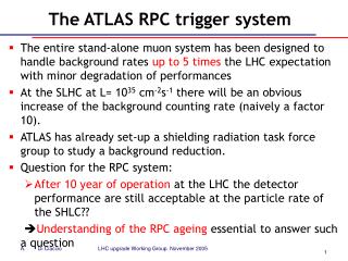
Central Trigger System • Central Trigger Processor (CTP) - Trigger Formation: receives trigger information from the Calorimeter and Muon processors (@ 40 MHz) and forms the Level-1 Accept. Latency of 100 ns. • TTC (Timing, Trigger and Control) partitions – Timing, Trigger distribution to all subsystems. ~40 TTC Partitions in ATLAS. • TTC partitions formed by: • one Local Trigger Processor(LTP) • TTC system itself: • one TTC-vi module • TTC optical conversion+distribution+fan-out (TTC-ex/tx/vx, TTC-oc) • TTC-rx ASIC: recover TTC signals at subdetectors’ front-end electronics. • BUSY feed-back tree, based on ROD_BUSY module. Busy fed back to CTP, to throttle L1-A generation. LECC-2004, Boston, 13-17 Sep
Central Trigger Processor - Overview • Trigger Inputs: • Receive trigger information from muon and calorimeter trigger processors: • Multiplicities for muons, electrons/photons, taus/hadrons and jets. • Flags for ∑ET, ETmiss, ∑ETjet. • Other external inputs (beam-pickups, cosmic triggers, min-bias + luminosity…) • Synchronize and align inputs coming from different sources. • Level-1 Accept formation: • Implement trigger menu: Level-1 Physics Selection: • Flexible: Combination of all trigger information inputs. • Easy to change/reload. • Latency ~ 100 ns. (out of total Level-1 Latency < 2.5 µs (max) ) • Generate dead-time: front-end electronics should sustain 100 kHz L1-A accept rate • Receive BUSY from sub-detectors, to throttle L1-A generation. • Other signals: Trigger Type, Event Counter Reset. • Send info to LVL2+DAQ, upon Level-1 Accept LECC-2004, Boston, 13-17 Sep
CTP – Design LECC-2004, Boston, 13-17 Sep
CTP – Machine Interface (CTP_MI) • Functionality: • Timing Module: receives timing signals (clock, Orbit) from LHC (via TTC-mi) or generate them locally. • Generates ECR (Event Counter Reset) and SYN (Synchronization signals). • Distributes timing signals over COM bus to all other CTP modules. • Receives, monitor and mask BUSY signals (Same functionality as ROD_BUSY module). Busy sources: BUSY signal collected over backplane (from CTP_OUT modules), external (NIM) inputs and internally generated. • Implementation: • Altera Cyclone FPGAs. • CERN High-Performance Time-Digital Converter for Phase Measurement. LECC-2004, Boston, 13-17 Sep
CTP – Machine Interface (CTP_MI) • Status: • CTP_MI tested successfully: available for test-beam. LECC-2004, Boston, 13-17 Sep
Test Memory MONITORING VME INTERFACE Trigger Inputs<31..0> VME_BUS LVDS RX Pipeline FPGA SWITCH MATRIX PIT_BUS<159..0> HPTDC VME INT. (SSTL single-ended) BCK x4 ICLK Clock Adjustment PHOS4 ORBIT CTP – Input Module (CTP_IN) • Functionality: • Receive trigger inputs from Calorimeter & Muon triggers and others (external triggers + calibrations).(3 CTP_IN modules, 4x31 signals each module=372 trigger inputs) • Synchronize w.r.t. (local) clock, align w.r.t. (same) bunch crossing + check parity. (Programmable Pipeline Length 1-63 steps = 1575 ns) • Select (160) trigger inputs to be sent to PIT bus. (Switch Matrix) • Store trigger inputs + provide (test) inputs. (Test Memory) • Scalers/counters to monitor integrated trigger inputs. (Monitoring) • Phase measurement of trigger inputs w.r.t. local clock. (HPTDC) VME INT. LECC-2004, Boston, 13-17 Sep
VME INT. Test Memory MONITORING VME INTERFACE Trigger Inputs<31..0> VME_BUS LVDS RX Pipeline FPGA SWITCH MATRIX PIT_BUS<159..0> HPTDC VME INT. (SSTL single-ended) BCK x4 ICLK Clock Adjustment PHOS4 ORBIT CTP – Input Module (CTP_IN) • Implementation: • Trigger inputs transmission: paralell LVDS @ 40 MHz • PipelineBlock: Altera Stratix FPGA • SwitchMatrix: Lattice XPLD • TestMemory: Cypress Dual Port Memory. Storage capacity for 18 orbits • Monitoring: Altera Cyclone FPGA • Phase measurement: HPTDC= CERN High Performance Time to Digital Converter • (fine) Adjustment of local clock w.r.t. LHC machine clock (BCK). (CERN ASIC PHOS4. 1 ns resolution) LECC-2004, Boston, 13-17 Sep
CTP – Input Module (CTP_IN) • Status: • CTP_IN internal operation tested successfully: available for test-beam. • Being tested: External connections + monitoring. LECC-2004, Boston, 13-17 Sep
Control Histogramming PIT bus Decoding (LUT) (readout) FIFO VME N N-1 Memory BCID Counter Data Address x4 CTP – Monitoring module (CTP_MON) • Functionality (&Implementation): • Receive trigger inputs from PIT bus coming from CTP_IN. (SSTL-2) • Select and decode trigger inputs to be monitored (Max: 160. LUT Block: Altera APEX FPGA.) • Histogram each selected trigger input bunch-by-bunch. Ie: for each trigger input, form histogram occupancy vs. Bunch Counter ID. (30-bit deep memories, hence ~26 hours without overflow, for a trigger input always on. 2 MByte memories (160x3564x30), implemented with Altera Stratix FPGAs) • Readout FIFOs: IDT. Readout Control +VME interface: Altera APEX FPGA. LECC-2004, Boston, 13-17 Sep
CTP – Monitoring module (CTP_MON) • Status: • CTP_MON internal operation tested successfully: available for test-beam. • Currently only one (out of four) Stratix devices. (expensive) LECC-2004, Boston, 13-17 Sep
CTP – Core module (CTP_CORE) • Functionality • Receive (160) trigger inputs from PIT bus, coming from CTP_IN. • Implement Trigger Menu: (160) trigger inputs are combined into (a set of 256) trigger items: • Each trigger item is a combination of (conditions on) trigger inputs. Ex: One (or more) μ>20 GeV AND Missing Transverse Energy>20 GeV AND Filled Bunch (from Beam-pickups) • Each item can be masked, and prescaled independently. (also Priority (high/low) is assigned, for complex dead-time algorithm) • Form Level-1 Accept = OR of all trigger items. (after mask and scaling) • Form Trigger Type word. • Trigger result (Level-1 Accept and Trigger Type) sent to COM bus (to CTP_OUT) • Add preventive dead-time (two mechanisms: simple and complex algorithms) • For each accepted event: • Sends Region-of-Interest (ROI) information to ROI-Builder, to be used by Level-2 Trigger. • Sends information of trigger formation (trigger inputs and trigger items before/after masking+prescaling) to Read-Out System (ROS) to be collected by DAQ system. • Foreseen: Add Universal Time (LHC/GPS ± 25ns) to DAQ readout. LECC-2004, Boston, 13-17 Sep
LUT CAM Mask Prescaling Priority 160 256 256 Trigger Conditions Trigger Inputs CTP – Core module (CTP_CORE) • Implementation: • LUT(Look-Up-Table) + CAM (Content-Addressable-Memory) to form trigger menu (Xilinx Virtex-II FPGA) Trigger Items • (Three) ALTERA Stratix FPGAs for Veto+Prescaler, Readout+Monitoring, UTC Time • Physics capabilities of (implementation of) Trigger Menu: • Large number of trigger inputs (160, greater currently foreseen) • Large number of (individual) trigger items. (256, greater than trigger tables currently foreseen) • Maximum flexibility in forming trigger items: • Combination of ANY number of trigger inputs. • LUT mapping allows decoding of multiplicity triggers and encoded flags. • Programmable (download memories via VME access): Can change trigger menu quickly. LECC-2004, Boston, 13-17 Sep
CTP – Core module (CTP_CORE) • Status: • CTP_CORE manufactured, testing has begun. • Trying to move to test-beam a.s.a.p., to participate in the 5-11 October, 25 ns run. LECC-2004, Boston, 13-17 Sep
CTP – Output Module (CTP_OUT) • Functionality: • Receive timing and trigger signals from COM bus and fan-out to the sub-detectors (LTPs) (4 CTP_OUT module fans out to five LTPs = 20 cables) • Receive, monitor and mask BUSY signals from sub-detectors. (Same functionality as ROD_BUSY module). Assert BUSY-ored onto COM bus. • Receive Calibration Requests from sub-detectors and send it to CTP_CAL module. • Implementation: • BUSY logic +VME interface implemented with ALTERA Cyclone FPGA. Fan-out using LVDS. • Status: • (one prototype) tested successfully in the lab. Ready for test-beam. LECC-2004, Boston, 13-17 Sep
CTP – Calibration Module (CTP_CAL) • Functionality: • Handle Calibration Requests from detectors: • Some ATLAS sub-detectors have expressed need for calibration triggers during orbit gap. • Mechanism to handle this: Assign one orbit gap to each sub-detector. If a CAL_REQ signal is received (via CTP_OUT) at the correct orbit, then send signal to CTP_IN→CTP_CORE to generate L1A. (up to detectors to fire calibration signals at appropriate time, via LTP+TTC-vi) • Patch-panel for external trigger inputs to be sent to CTP_IN. Example: Beam-pickup signals, luminosity triggers, minimum-bias triggers, cosmics, etc… • Implementation: • Design of CTP_CAL still to be done. • Not needed for test-beam. LECC-2004, Boston, 13-17 Sep
CTP – Buses/Backplanes • COM bus: • Timing signals(BCK, ORB, SYN) : From CTP_MI to all modules. Point-to-point LVPECL differential fan-out. • Trigger signals(L1A, TTYPE,PRE) : From CTP_CORE to (4) CTP_OUT and CTP_CAL. Multi-drop differential bus, terminated on backplane. LVPECL. • Busy: accessible to all modules. Wired-OR signaling. Multipoint-LVDS, terminated on backplane. • PIT bus: • 160 PIT (pattern-in-time) trigger inputs from CTP_IN to CTP_CORE+CTP_MON. • Short bus: single ended, multi-drop bus, SSTL-2 like. Terminated on CTP_CORE//CTP_MON. • CAL bus: • Calibration request signals: From (4) CTP_OUT to CTP_CAL. • LVDS point-point, terminated on CTP_CAL. LECC-2004, Boston, 13-17 Sep
COM backplane PIT/CAL Backplane CTP – Backplanes • Implementation: • Pre-layout simulation of signal propagation & integrity: IBIS models+SigXplorer (CADENCE) • COM Backplane: mounted at the back of J0 connector. 4 layers PCB, controlled impedance. • PIT/CAL Backplane: mounted in J5/J6 position. 9 layers PCB, controlled impedance. • Backplanes manufactured and tested ok. LECC-2004, Boston, 13-17 Sep
LTP - Local Trigger Processor See poster presentation by Philippe Farthouat • Functionality: • “Programmable input/output switch for timing & control signals” - Allows to implement two Run Modes: • Global Mode: interface between CTP and TTC partitions. • Stand-Alone Mode: LTP replaces CTP. • Total number in ATLAS ~ 40, one per partition. LTPs can be daisy chained. (1 master, N slaves) • Very flexible module, (also) useful for testing. • Implementation: • Altera MAX CPLDs + RAMs for pattern-generator. 6U VME, double width. • Status: • 6 prototypes produced and tested. Started to be used at test-beam. LECC-2004, Boston, 13-17 Sep
ROD_BUSY • Functionality: • Receives 16 input BUSY signals from detector’s RODs (Read-Out Drivers) and/or other ROD_BUSYs. • Mask faulty inputs. • Form overall BUSY-OR of masked inputs. • Monitoring: • Store the history of each BUSY input. (up to 3.3 s) • Generate Interrupt Request if BUSY-OR is asserted for longer than a pre-set time limit. • ROD_BUSYs can be daisy-chained, until feeding an LTP. Total number in ATLAS ~ 60. • Implementation: • Altera MAX CPLDs + FIFOs for monitoring. 6U VME. • Status: • 12 Final modules produced. Being used at Test-Beam. LECC-2004, Boston, 13-17 Sep
Plans for test-beam • Main Goal: • Participate in the 5-11 October 25 ns run. • Integration with Muon trigger. (done before with prototype system) • Integration with Calorimeter trigger. NEW! • Align Muon + Calorimeter inputs, form FIRST combined (Cal+Muon) complete self-trigger chain: • particle detection at calorimeters + muon detectors • up the trigger chain until forming Level-1 Accept in CTP • initiating DAQ readout of all sub-detectors • Timing and Trigger distribution via LTPs. LECC-2004, Boston, 13-17 Sep