Download

1 / 37
370 likes | 443 Views
Flow Cytometry Basics. James Marvin Director, Flow Cytometry Core Facility University of Utah Health Sciences Center Office 801-585-7382 Lab 801-581-8641 Utahflowcytometry.wordpress.com jmarvin@cores.utah.edu. Seventeen- colour flow cytometry: unravelling the immune system

E N D
Flow Cytometry Basics James Marvin Director, Flow Cytometry Core Facility University of Utah Health Sciences Center Office 801-585-7382 Lab 801-581-8641 Utahflowcytometry.wordpress.com jmarvin@cores.utah.edu
Seventeen-colour flow cytometry: unravelling the immune system Nature Reviews Immunology, 2004 # of colors 1 2 3 4 5 6 7 8 9 10 # of plots 1 1 3 6 10 15 21 28 36 45
Flow CytometryApplications • Total protein • Lipids • Surface charge • Membrane fusion/runover • Enzyme activity • Oxidative metabolism • Sulfhydryl groups/glutathione • DNA synthesis • DNA degradation • Gene expression • Phagocytosis • Microparticle analysis • RNA detection • Immunophenotyping • DNA cell cycle/tumor ploidy • Membrane potential • Ion flux • Cell viability • Intracellular protein staining • pH changes • Cell tracking and proliferation • Sorting • Redox state • Chromatin structure The uses of flow in research has boomed since the mid-1980s, and is now the gold standard for a variety of applications
Section I Background Information on Flow Cytometry
Many components to a successful assay Experimental Design “One on One” Presentation “Data Analysis” Analysis “Data Analysis” Instrumentation “Flow Basics” Advanced Compensation • Sample Procurement • Sample preparation • Fix/Perm • Fluorophore • Controls • Isotype? • Single color • FMO • Interpretation • Mean, Median • % + • CV • SD • Signal/Noise • Gating • Appropriate Lasers • Appropriate Filters • Instrument Settings • Lin vs Log • Time • A, W, H • Doublet discrimination • Interpretation • Mean, Median • % + • CV • SD • Signal/Noise • Gating • Histogram • Dot Plot • Density Plot • Overlay • Bar Graph
Cytometry/Microscopy Localization of antigen is possible Poor enumeration of cell subtypes Limiting number of simultaneous measurements Flow Cytometry No ability to determine localization (traditional flow cytometer) Can analyze many cells in a short time frame (30k/sec) Can look at numerous parameters at once (>20 parameters) Cytometry vs. Flow Cytometry
Section II The 4 Main Components of a Flow Cytometer
What Happens in a Flow Cytometer? Interpretation Fluidics Electronics Interrogation
Hydrodynamic Focusing Gaussian- A “bell curved” normal distribution where the values and shape falls off quickly as you move away from central, most maximum point. Sample Sheath Sheath Sample Core Stream Laser Focal Point Incoming Laser High Differential or “turbulent flow” Low Differential
Low pressure High pressure
Acoustic focusing Acoustic focusing uses ultrasonic radiation pressure (>2 MHz) to transport particles into the center of the sample stream
Fluidics Recap • Purpose is to have cells flow one-by-one past a light source • Cells are “focused” due to hydrodynamic focusing • Turbulent flow, caused by clogs or fluidic instability can cause imprecise data
Fluidics Electronics Interpretation Interrogation What Happens in a Flow Cytometer? Interpretation Fluidics Electronics Interrogation
What Happens in a Flow Cytometer (Simplified) Flow Cell- the place where hydrodynamically focused cells are delivered to the focused light source
Scatter Fluorescence VS Light collection • Collected photons are product of excitation with subsequent emission determined by fluorophore • 350nm-800nm • Readout of intrinsic (autofluorescence) or extrinsic fluorescence (intentional cell labeling) • Collected photons are the product of laser light scattering or bouncing off cells • FSC=rough estimate of size • SSC=internal complexity/granularity • Information associated with physical attributes of cells (size, granularity, refractive index)
The amount of light scattered by any particle is directly proportional to the diameter of the particle and inversely proportional to the wavelength of the light being used to detect it. Violet-SSCvsBlue-SSC Noise/Debris 110nm particles 408nm SSC 488nm SSC
Granulocytes Lymphocytes SSC Monocytes RBCs, Debris, Dead Cells FSC Why Look at FSC v. SSC • Since FSC ~ size and SSC ~ internal structure, a correlated measurement between them can allow for differentiation of cell types in a heterogenous cell population Dead LIVE
Mass Cytometry Instead of fluorophore labelled antibodies, Cytof uses Isotope labelled antibodies No spectral overlap in detectors CYTOF
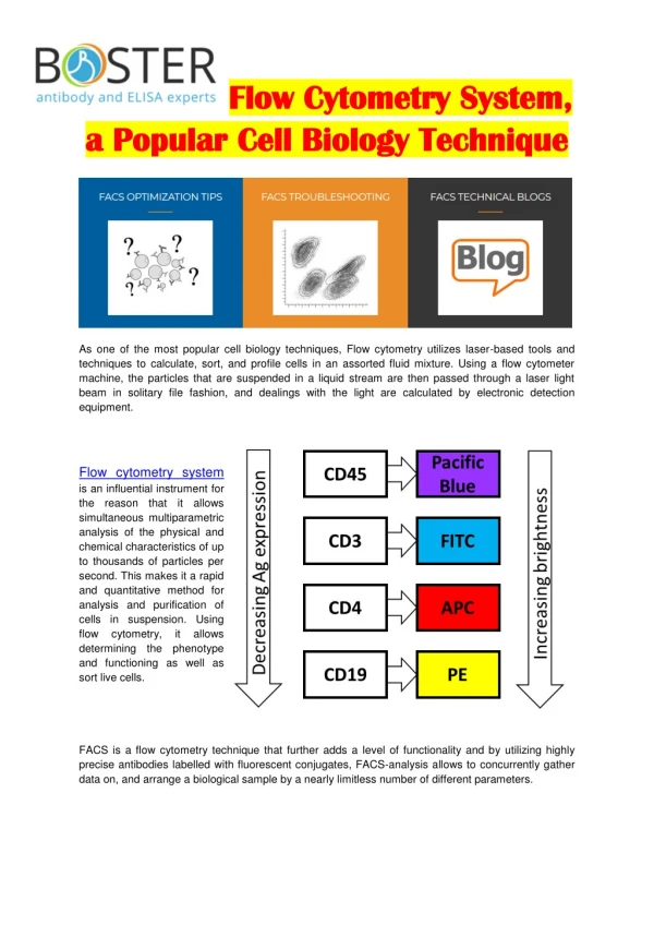
Compensation • Fluorochromes typically fluoresce over a large part of the spectrum (100nm or more) • A detector may “see” fluorescence from more than 1 fluorochrome. (referred to as bleed over) • You need to “compensate” for this bleed over so that 1 detector reports signal from only 1 fluorochrome
Compensation matrix Compensation matrix for 8 color analysis
Multi-laser Instruments and pinholes Implications- -Can separate completely overlapping emission profiles if originating off different lasers -Significantly reduces compensation
Spatial separation Blue Laser Excitation Blue and Yellow Laser Excitation No Compensation Applied 585/20 Blue 585/20 Yellow 530/20 Blue 530/20 Blue
Interrogation Recap • A focused light source (laser) interrogates a cell and scatters light • That scattered light travels down a channel to a detector • FSC ~ size and cell membrane integrity • SSC ~ internal cytosolic structure • Fluorochromes on/in the cell will become excited by the laser and emit photons • These photons travel down channels and are steered and split by dichroic (LP/SP) filters
Fluidics Interrogation Electronics Interpretation What Happens in a Flow Cytometer? Interpretation Fluidics Electronics Interrogation
Electronics • The “electronics” process light signal intensities and convert them to a proportional digitized value/# that the computer can graph
Photons -> Photoelectrons -> Electrons Photoelectric Effect Einstein- Nobel Prize 1921 A photomultiplier tube, useful for light detection of very weak signals, is a photoemissive device in which the absorption of a photon results in the emission of an electron. These detectors work by amplifying the electrons generated by a photocathode exposed to a photon flux.
Pulse Area Pulse Height Pulse Width Measurements of the Pulse Measured Current at detector Time
Does voltage setting matter? 292 272 Voltage=362 252 522 -Voltage doesn’t change sensitivity or laser power -All your doing is changing the amplification of the signal -Caveat- there is large “sweet spot” of PMT voltage, outside of this range you may run the risk of non linear amplification
Electronics Recap • Photons ElectronsVoltagepulseDigital #
Fluidics Interrogation Electronics Interpretation What Happens in a Flow Cytometer? Interpretation Fluidics Electronics Interrogation