Download
1 / 52
720 likes | 2.04k Views
Tutorial on Harmonics Modeling and Simulation. Chapter 2 Harmonics and Interharmonics Theory. Contributors: G. W. Chang and A. Testa. Outline. Introduction Fourier Series and Analysis Basic Definition of Harmonic and Interharmonic Quantities Harmonic and Interharmonic Indices

E N D
Tutorial on Harmonics Modeling and Simulation Chapter 2Harmonics and Interharmonics Theory Contributors: G. W. Chang and A. Testa
Outline • Introduction • Fourier Series and Analysis • Basic Definition of Harmonic and Interharmonic Quantities • Harmonic and Interharmonic Indices • Power Factor under Distorted Situation • Power System Response to Harmonics and Interharmonics • Solutions to Harmonics and Interharmonics • Summary
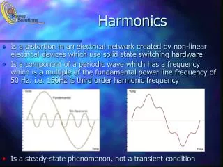
Introduction • With the widespread proliferation of nonlinear devices such as power electronics and arc furnace loads, significant amounts of harmonic and interharmonic currents are being injected into the power system. • Harmonic and interharmonic currents not only disturb loads that are sensitive to waveform distortion, but also cause many undesirable effects on power system components.
Introduction • Harmonic Sources(nonlinear loads) • Single-phase loads: fluorescent lights, personal computers • Three-phase loads: arc furnaces, ac/dc converters
Introduction • Harmonics and interharmonics are usually defined as periodic steady-state distortions of voltage and/or current waveforms in the power system. • In the harmonics and interharmonics polluted environment, the theory regarding harmonic and interharmonic quantities needs to be defined to distinguish from those quantities defined for the system fundamental frequency.
Fourier Series and Analysis • Periodic Function • Orthogonal Function e.g. Period: T
Fourier Series and Analysis By the use of orthogonal relations, we have
Fourier Series and Analysis • Fourier analysis is a process of the de-composition for any distorted period wave shape into a fundamental and a series of harmonics. • Advantages of Fourier series and analysis: -Useful for studying electrical networks which contain non- sinusoidal voltages and currents - The frequency components are harmonics of the fundamental frequency - For linear networks, treat each harmonic separately by using phasor analysis (frequency domain), then combine the results and convert back to the time domain waveform
Fourier Series and Analysis • Complex Form • Waveform Symmetry - Even function: (no sine terms) - Odd function: (no cosine terms) - Half-wave symmetry: (no even harmonics)
Fourier Series and Analysis • Fourier Transform • Discrete Fourier Transform: T frequency-domain spectrum and the time-domain function are both periodic sampled functions with N samples per period, Fourier transform pair becomes is the so-called spectrum of which is assumed to be one cycle of a periodic signal. k, n = 0, 1, ..., N-1,
Fourier Series and Analysis • The angular frequency resolution of the spectrum is determined by the length of the signal as . Thus, if T is selected as one period of , the outcome spectrum will only show components that are integer multiples of the fundamental frequency, which are defined as harmonics. • If the data length is selected as p cycles (p>1 and is an integer) of the fundamental, the frequency resolution will change to . This implies that once we use more than one fundamental cycle to perform the DFT, it also becomes possible to obtain components at frequencies that are not integer multiples of the fundamental.
Fourier Series and Analysis • The non-integer order components, according to the IEC-61000-2-1 definition, are called interharmonics. • The DFT is often used in harmonics and interharmonics measurement. Fast Fourier transform (FFT) algorithms are very fast methods for performing the DFT calculations. • There are pitfalls of the aliasing, the spectral leakage, and the picket-fence effect, when applying FFT for harmonics and interharmonics computations.
Basic Definition of Harmonic and Interharmonic Quantities • The definition of a harmonic can be stated as: A sinusoidal component of a periodic wave having a frequency that is an integer multiple of the fundamental frequency. • The interharmonics are defined as those components with frequencies between two consecutive harmonics or those components whose frequencies are not integer multiples of the fundamental power frequency. • One special subset of interharmonics that have frequency values that are less than that of the fundamental frequency is called sub-harmonics.
Basic Definition of Harmonic and Interharmonic Quantities • One major source of harmonics in the power system is the static power converter. Under ideal operating conditions, the current harmonics generated by a p-pulse line-commutated converter can be characterized by and e.g. Such harmonics are usually termed as characteristic harmonics. • Non-characteristic harmonics are typically categorized as those integer frequency components other than characteristic ones.
Basic Definition of Harmonic and Interharmonic Quantities • The power electronic equipment with double conversion systems that connects two AC systems with different frequencies through a DC link can be an interharmonic source. Variable speed drives, HVDC, and other static frequency converters are typical examples of this class of sources. Other sources of interharmonics include time-varying loads such as welder machines and arc furnaces. • There are various causes that could lead to the interharmonic components. One example is a signal that actually contains in the frequency domain with a component whose frequency is non-integer multiples of the fundamental frequency.
Basic Definition of Harmonic and Interharmonic Quantities • There are cases where the interharmonic components are produced by the picket-fence effect when applying the FFT, due to sampling the signal with a spectral leakage. The picket-fence effect occurs when the analyzed waveform includes spectral components which are not an integer multiple of the FFT fundamental frequency (i.e. the reciprocal of the window length in time). Such effect may lead to a situation where the frequency resolution (i.e. the sampled frequency interval) of the spectrum is not observable for certain frequencies. • A frequency component lying between two FFT consecutive harmonics will affect these two harmonic magnitudes and also may cause the spectral leakage.
Basic Definition of Harmonic and Interharmonic Quantities Frequency resolution = 30 Hz
Basic Definition of Harmonic and Interharmonic Quantities Interharmonics: p1: the pulse number of the rectifier section p2: the pulse number of the output section m and n: integers fs: the power frequency f0: the inverter output frequency
Basic Definition of Harmonic and Interharmonic Quantities • Sub-harmonics have frequency values that are less than that of the fundamental frequency. Lighting flicker is one indication of the presence of interharmonics around the fundamental power frequency (including sub-harmonics), which is due to the voltage fluctuations with frequencies being much less than the system fundamental frequency. A well-known source of the voltage fluctuations that cause light flicker is the arc furnace.
Electric Quantities Under Non-sinusoidal Situation • Instantaneous voltage and current • Instantaneous power • Average power • RMS voltage and current • Apparent power • Reactive power • Distortion power • Total power factor
Electric Quantities Under Non-sinusoidal Situation • Instantaneous Voltage and Current • Instantaneous and Average Power
Electric Quantities Under Non-sinusoidal Situation • RMS Voltage and Current • Apparent, Reactive, and Distortion Power
Electric Quantities Under Non-sinusoidal Situation • Power at sinusoidal situation • Total power factor No consensus in the definition and physical meaning on reactive and distortion power.
Phase Sequences of Harmonics and Interharmonics • Phase sequences of harmonics • For variable frequency drives and motors with fluctuating loads, interharmonics can have either positive or negative sequence and are rarely zero sequence. The general rule is that the sequence of the interharmonc component is the same as that of the supply system harmonic components being modulated.
Zero sequence Negative sequence Positive sequence Phase Sequences of Harmonics and Interharmonics 3h-1: negative sequence 3h: zero sequence 3h+1:positive sequence h = 1, 2,…
Harmonic Indices • Total Harmonic Distortion (THD) • Total Demand Distortion (TDD) • Telephone Influence Factor (TIF) • VT and IT Products • C-Message Weighted Index • Transformer K-Factor and Harmonic Loss Factor • Distortion Power Factor
Harmonic Indices • Total Harmonic Distortion (THD) • Total Interharmonic Distortion (TIHD) Λ is the set of all interharmonics components under considerations.
Harmonic Indices • Total Demand Distortion (TDD) is the maximum demand load current (15 or 30 minute demand) at fundamental frequency at the point of common coupling (PCC), calculated as the average current of the maximum demands for the previous twelve months.
Harmonic Indices • Telephone Influence Factor (TIF) is a weighting accounting for audio and inductive coupling effects at the h-th harmonic frequency. • VT and IT Products
Harmonic Indices • C-Message Weighted Index • K-Factor and Harmonic Loss Factor
Harmonic Indices • Distortion Power Factor (PFD)
Power System Response to Harmonics and Interharmonics • Power System Response to Harmonics and Interharmonics - Series resonance - Parallel resonance - Distributed resonance
Power System Response to Harmonics and Interharmonics Series resonance Parallel resonance Distributed resonance
Power System Response to Harmonics and Interharmonics Parallel Resonace
Power System Response to Harmonics and Interharmonics Series Resonance
Solutions to Harmonics and Interharmonics • Remedial methods - Passive Filters - Phase Multiplication - Special Designed Transformer (e.g. zig-zag) - Active Filters • Preventive method - Harmonic Standards * IEEE 519-1992 * IEC 61000-3-6
Remedial Methods • Series filter – characterized as a parallel resonant and blocking type with a high impedance at its tuned frequency • Parallel filter – characterized as a series resonant and trap type with a low impedance at its tuned frequency Series filter Parallel filter
Remedial Methods Passive filter
Remedial Methods Phase Multiplication
Remedial Methods Phase Multiplication
Remedial Methods Special Designed Transformer
Remedial Methods Active filter
Remedial Methods Active filter
Preventive Methods (Harmonic Standards) IEEE 519-1992 Current Distortion Limits for General Distribution Systems
Preventive Method (Harmonic Standards) IEEE 519-1992 Recommended Voltage Distortion Limits
Preventive Method (Harmonic Standards) IEC 61000-3-6: Compatibility levels for harmonic voltages (in percent of the nominal voltage) in LV and MV power systems
Preventive Method (Harmonic Standards) IEC 61000-3-6:Indicative values of planning levels for harmonic voltage (in percent of the nominal voltage) in MV, HV and EHV power systems