Download
1 / 26
310 likes | 375 Views
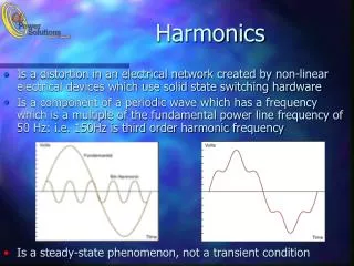
Harmonics. Causes, Effects, Solutions Including: K-Factor Transformers Harmonic Mitigating Transformers. What are harmonics?. HARMONICS: A sinusoidal waveform with a frequency that is an integral multiple of the fundamental frequency. 60hz Fundamental 120hz 2nd Harmonic

E N D
Harmonics Causes, Effects,Solutions Including: K-Factor Transformers Harmonic Mitigating Transformers
What are harmonics? HARMONICS: A sinusoidal waveform with a frequency that is an integral multiple of the fundamental frequency. 60hz Fundamental 120hz 2nd Harmonic 180hz 3rd Harmonic 240hz 4th Harmonic etc... Note: Each individual harmonic is sinusoidal.
Sum of 60hz & 300hz (Fundamental & 5th Harmonic)
Where Do Harmonics Originate? Harmonics primarily originate in electronic power converters. These can be found in: 1. Switch Mode Power Supplies 2. Electronic Ballasts 3. Variable Frequency Drives 4. Oven and Furnace Controls 5. Rectifier Circuits
Problems Created By Harmonic Currents 1. Overheated Neutrals 2. Overheated Transformers 3. Malfunctioning of Equipment due to excessive voltage distortion 4. Burned-out Motors 5. Tripped Circuit Breakers 6. Blown Fuses
Triplen Harmonics Triplen harmonics include the 3rd harmonic and all the odd multiples of the 3rd. Example: 3rd, 9th, 15th, 21st, 27th, 33rd, etc Note: Triplen harmonics tend to add up in the three phase neutral conductor.
Effects of Harmonics on Transformers 1. Increased temperature rise 2. Increased neutral current flow 3. Increased core losses 4. Increased sound level 5. Decreased efficiency
K-Factor A measure of a transformer’s ability to withstand the heating effects of non-sinusoidal harmonic currents created by much of today’s electronic equipment. The stray losses of the transformer are multiplied by the K-Factor of the load resulting in increased heating of the unit.
Transformer Conductor Losses Transformer conductor losses are composed of AC and DC losses. AC losses = stray losses DC losses = I^2 x R Total conductor losses = AC + DC losses Note: Stray losses get multiplied by the K-factor of the load.
Temperature Rise Example Typical 75kVA (DOE 2016) 75 kVA, 3-Ph, 480 - 208Y/120, 150 degree rise Total conductor losses at K-1 (linear load) = 2314 + 116 = 2430 If K=20 (non-linear load), new conductor losses are: 2314 + (20 x 116) = 4634 watts Rise @ K-1 = 150 degrees C Rise @ K-20 = 238 degrees C
Two Solutions to Harmonic Problems 1. K - Rated Transformers (traditional) 2. Harmonic Mitigating Transformers (zig-zag)
K-Rated Transformers K - Rated or Non-Linear transformers do not eliminate harmonics! They are only designed to tolerate the heating effects of harmonics created by much of today's electronic equipment.
K-Rated, continued K-rated transformers are traditional Delta-Wye transformers They are designed with lower flux densities and no-load losses as well as lower I²R losses resulting in a larger and heavier unit. They do not eliminate or cancel harmonics (they only tolerate the effects)
K-Factor Features • Available in K-Factors of 4, 13, and 20 • Aluminum or Copper windings. • Available temperature rises of 150 or 115 • UL listed and CSA certified
K-Factor and DOE 2016 As of January 1, 2016 K-Rated transformers must comply to the efficiency standards (DOE 2016) of the National Energy Bill They are only required to comply with a connected linear load condition of K1 (no harmonics)
Harmonic Mitigating Transformers How do they work? They consist of a Delta primary and a Zig-Zag secondary. The Zig-Zag secondary causes a phase shift in the triplen harmonics which results in a canceling effect. This prevents the triplen harmonic losses from being coupled back into the primary and results in cooler operation and increased energy efficiency.
What is Zig-Zag Winding? The secondary winding on each magnetic leg of the core is wound in two separate sections. These sections are then transposed between different legs of the core to create the zig-zag secondary. Each 120 v output of the transformer consists of two sections from different magnetic legs resulting in a magnetic phase shift
Diagram: Delta primary and Zig-Zag secondary (Zero degree angular displacement)
Harmonic Mitigating Catalog Numbers H3030K0014BCS 30 KVA H3045K0014BCS 45 KVA H3075K0014BCS 75 KVA H3112K0014BCS 112.5 KVA H3150K0014BCS 150 KVA H3225K0014BCS 225 KVA
Harmonic Mitigating Benefits 1. Unlike K-Rated transformers, Mitigating transformers actually treat the triplen harmonics in the zig-zag secondary winding 2. Reduce supply voltage flat topping caused by non-linear loads 3. Improve overall power factor of supply system 4. Suitable for K-Factor loads 5. Improved energy efficiency (Meet DOE 2016 at K-1 load)
Mitigating Transformer Features Copper windings Taps: 2 x 2.5% ANFC and BNFC 220 Degree C insulation system with 150 Degree C rise UL listed and CSA certified Zero degree angular displacement between Primary and Secondary windings (compared to thirty degrees in a traditional delta to wye transformer)
Important Points to Remember Harmonic mitigating transformers don’t treat harmonics or neutral current until they reach the transformer windings Transformer has 200% Neutral Bar Neutral conductor from transformer to Load Panel should be sized at 200%
Questions or CommentsTech Service contact number:800-334-5214 option 1