Download
1 / 49
500 likes | 713 Views
CS 268: Lecture 10 Router Design and Packet Lookup. Ion Stoica Computer Science Division Department of Electrical Engineering and Computer Sciences University of California, Berkeley Berkeley, CA 94720-1776. . . . . . . IP Router. A router consists

E N D
CS 268: Lecture 10Router Design and Packet Lookup Ion Stoica Computer Science Division Department of Electrical Engineering and Computer Sciences University of California, Berkeley Berkeley, CA 94720-1776
. . . . . . IP Router • A router consists • A set of input interfaces at which packets arrive • A se of output interfaces from which packets depart • Router implements two main functions • Forward packet to corresponding output interface • Manage congestion istoica@cs.berkeley.edu
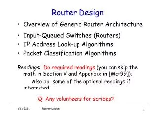
Overview • Router Architecture • Longest Prefix Matching istoica@cs.berkeley.edu
Generic Router Architecture • Input and output interfaces are connected through a backplane • A backplane can be implemented by • Shared memory • Low capacity routers (e.g., PC-based routers) • Shared bus • Medium capacity routers • Point-to-point (switched) bus • High capacity routers input interface output interface Inter- connection Medium (Backplane) istoica@cs.berkeley.edu
Speedup • C – input/output link capacity • RI – maximum rate at which an input interface can send data into backplane • RO – maximum rate at which an output can read data from backplane • B – maximum aggregate backplane transfer rate • Back-plane speedup: B/C • Input speedup: RI/C • Output speedup: RO/C input interface output interface Inter- connection Medium (Backplane) C RI RO B C istoica@cs.berkeley.edu
Function division • Input interfaces: • Must perform packet forwarding – need to know to which output interface to send packets • May enqueue packets and perform scheduling • Output interfaces: • May enqueue packets and perform scheduling input interface output interface Inter- connection Medium (Backplane) C RI RO B C istoica@cs.berkeley.edu
Three Router Architectures • Output queued • Input queued • Combined Input-Output queued istoica@cs.berkeley.edu
Output Queued (OQ) Routers • Only output interfaces store packets • Advantages • Easy to design algorithms: only one congestion point • Disadvantages • Requires an output speedup of N, where N is the number of interfaces not feasible input interface output interface Backplane RO C istoica@cs.berkeley.edu
Input Queueing (IQ) Routers • Only input interfaces store packets • Advantages • Easy to built • Store packets at inputs if contention at outputs • Relatively easy to design algorithms • Only one congestion point, but not output… • need to implement backpressure • Disadvantages • In general, hard to achieve high utilization • However, theoretical and simulation results show that for realistic traffic an input/output speedup of 2 is enough to achieve utilizations close to 1 input interface output interface Backplane RO C istoica@cs.berkeley.edu
Combined Input-Output Queueing (CIOQ) Routers • Both input and output interfaces store packets • Advantages • Easy to built • Utilization 1 can be achieved with limited input/output speedup (<= 2) • Disadvantages • Harder to design algorithms • Two congestion points • Need to design flow control • An input/output speedup of 2, a CIOQ can emulate any work-conserving OQ [G+98,SZ98] input interface output interface Backplane RO C istoica@cs.berkeley.edu
Generic Architecture of a High Speed Router Today • Combined Input-Output Queued Architecture • Input/output speedup <= 2 • Input interface • Perform packet forwarding (and classification) • Output interface • Perform packet (classification and) scheduling • Backplane • Point-to-point (switched) bus; speedup N • Schedule packet transfer from input to output istoica@cs.berkeley.edu
Backplane • Point-to-point switch allows to simultaneously transfer a packet between any two disjoint pairs of input-output interfaces • Goal: come-up with a schedule that • Meet flow QoS requirements • Maximize router throughput • Challenges: • Address head-of-line blocking at inputs • Resolve input/output speedups contention • Avoid packet dropping at output if possible • Note: packets are fragmented in fix sized cells (why?) at inputs and reassembled at outputs • In Partridge et al, a cell is 64 B (what are the trade-offs?) istoica@cs.berkeley.edu
Cannot be transferred because is blocked by red cell Cannot be transferred because output buffer full Head-of-line Blocking • The cell at the head of an input queue cannot be transferred, thus blocking the following cells Input 1 Output 1 Input 2 Output 2 Input 3 Output 3 istoica@cs.berkeley.edu
Solution to Avoid Head-of-line Blocking • Maintain at each input N virtual queues, i.e., one per output Input 1 Output 1 Output 2 Input 2 Output 3 Input 3 istoica@cs.berkeley.edu
Cell transfer • Schedule: ideally, find the maximum number of input-output pairs such that: • Resolve input/output contentions • Avoid packet drops at outputs • Packets meet their time constraints (e.g., deadlines), if any • Example: • Use stable matching • Try to emulate an OQ switch istoica@cs.berkeley.edu
Stable Marriage Problem • Consider N women and N men • Each woman/man ranks each man/woman in the order of their preferences • Stable matching, a matching with no blocking pairs • Blocking pair; let p(i) denote the pair of i • There are matched pairs (k, p(k)) and (j, p(j)) such that k prefers p(j) to p(k), and p(j) prefers k to j istoica@cs.berkeley.edu
Gale Shapely Algorithm (GSA) • As long as there is a free man m • m proposes to highest ranked women w in his list he hasn’t proposed yet • If w is free, m an w are engaged • If w is engaged to m’ and w prefers m to m’, w releases m’ • Otherwise m remains free • A stable matching exists for every set of preference lists • Complexity: worst-case O(N2) istoica@cs.berkeley.edu
Example men pref. list women pref. list • If men propose to women, the stable matching is • (1,2), (2,4), (3,3),(2,4) • What is the stable matching if women propose to men? 1 2 4 3 1 2 1 4 3 2 3 4 3 2 1 4 1 2 4 3 1 1 4 3 2 2 3 1 4 2 3 1 2 3 4 4 2 1 4 3 istoica@cs.berkeley.edu
OQ Emulation with a Speedup of 2 • Each input and output maintains a preference list • Input preference list: list of cells at that input ordered in the inverse order of their arrival • Output preference list: list of all input cells to be forwarded to that output ordered by the times they would be served in an Output Queueing schedule • Use GSA to match inputs to outputs • Outputs initiate the matching • Can emulate all work-conserving schedulers istoica@cs.berkeley.edu
a.1 1 a c.2 b.2 b.1 a.1 2 b c.1 a.2 c.1 3 c b.3 c.3 (b) a.1 1 a 1 a c.2 b.2 b.1 a.1 c.2 b.2 b.1 a.1 2 b 2 b c.1 a.2 c.1 a.2 b.3 3 b.3 c 3 c b.3 c.3 c.3 c.1 (c) (d) Example 1 a c.2 b.2 b.1 a.1 2 b c.1 a.2 3 c b.3 c.3 (a) istoica@cs.berkeley.edu
A Case Study[Partridge et al ’98] • Goal: show that routers can keep pace with improvements of transmission link bandwidths • Architecture • A CIOQ router • 15 (input/output) line cards: C = 2.4 Gbps (3.3 Gpps including packet headers) • Each input card can handle up to 16 (input/output) interfaces • Separate forward engines (FEs) to perform routing • Backplane: Point-to-point (switched) bus, capacity B = 50 Gbps (32 MPPS) • B/C = 50/2.4 = 20 istoica@cs.berkeley.edu
packet header Router Architecture istoica@cs.berkeley.edu
Update routing tables Router Architecture input interface output interfaces 1 Backplane Data in Data out 15 Set scheduling (QoS) state forward engines Network processor Control data (e.g., routing) istoica@cs.berkeley.edu
Router Architecture: Data Plane • Line cards • Input processing: can handle input links up to 2.4 Gbps • Output processing: use a 52 MHz FPGA; implements QoS • Forward engine: • 415-MHz DEC Alpha 21164 processor, three level cache to store recent routes • Up to 12,000 routes in second level cache (96 kB); ~ 95% hit rate • Entire routing table in tertiary cache (16 MB divided in two banks) istoica@cs.berkeley.edu
Router Architecture: Control Plane • Network processor: 233-MHz 21064 Alpha running NetBSD 1.1 • Update routing • Manage link status • Implement reservation • Backplane Allocator: implemented by an FPGA • Schedule transfers between input/output interfaces istoica@cs.berkeley.edu
Data Plane Details: Checksum • Takes too much time to verify checksum • Increases forwarding time by 21% • Take an optimistic approach: just incrementally update it • Safe operation: if checksum was correct it remains correct • If checksum bad, it will be anyway caught by end-host • Note: IPv6 does not include a header checksum anyway! istoica@cs.berkeley.edu
Data Plane Details: Slow Path Processing • Headers whose destination misses in the cache • Headers with errors • Headers with IP options • Datagrams that require fragmentation • Multicast datagrams • Requires multicast routing which is based on source address and inbound link as well • Requires multiple copies of header to be sent to different line cards istoica@cs.berkeley.edu
Control Plane: Backplane Allocator • Time divided in epochs • An epoch consists of 16 ticks of data clock (8 allocation clocks) • Transfer unit: 64 B (8 data clock ticks) • During one epoch, up to 15 simultaneous transfers in an epoch • One transfer: two transfer units (128 B of data + 176 auxiliary bits) • Minimum of 4 epochs to schedule and complete a transfer but scheduling is pipelined. • Source card signals that it has data to send to the destination card • Switch allocator schedules transfer • Source and destination cards are notified and told to configure themselves • Transfer takes place • Flow control through inhibit pins istoica@cs.berkeley.edu
The Switch Allocator Card • Takes connection requests from function cards • Takes inhibit requests from destination cards • Computes a transfer configuration for each epoch • 15X15 = 225 possible pairings with 15! patterns istoica@cs.berkeley.edu
Allocation Algorithm istoica@cs.berkeley.edu
The Switch Allocator • Disadvantages of the simple allocator • Unfair: there is a preference for low-numbered sources • Requires evaluating 225 positions per epoch, which is too fast for an FPGA • Solution to unfairness problem: random shuffling of sources and destinations • Solution to timing problem: parallel evaluation of multiple locations • Priority to requests from forwarding engines over line cards to avoid header contention on line cards istoica@cs.berkeley.edu
Summary: Design Decisions (Innovations) • Each FE has a complete set of routing tables • A switched fabric is used instead of the traditional shared bus • FEs are on boards distinct from the line cards • Use of an abstract link layer header • Include QoS processing in the router istoica@cs.berkeley.edu
Overview • Router Architecture • Longest Prefix Matching istoica@cs.berkeley.edu
Lookup Problem • Identify the output interface to forward an incoming packet based on packet’s destination address • Forwarding tables summarize information by maintaining a mapping between IP address prefixes and output interfaces • Route lookup find the longest prefix in the table that matches the packet destination address istoica@cs.berkeley.edu
12.82.100.101 128.16.120.111 Example • Packet with destination address 12.82.100.101 is sent to interface 2, as 12.82.100.xxx is the longest prefix matching packet’s destination address 128.16.120.xxx 1 12.82.xxx.xxx 3 12.82.100.xxx 2 … … 1 2 istoica@cs.berkeley.edu
Patricia Tries • Use binary tree paths to encode prefixes • Advantage: simple to implement • Disadvantage: one lookup may take O(m), where m is number of bits (32 in the case of IPv4) 1 0 001xx 2 0100x 3 10xxx 1 01100 5 1 0 0 1 0 1 1 2 0 0 3 0 5 istoica@cs.berkeley.edu
Lulea’s Routing Lookup Algorithm (Sigcomm’97) • Minimize number of memory accesses • Minimize size of data structure (why?) • Solution: use a three-level data structure istoica@cs.berkeley.edu
root heads genuine heads First Level: Bit-Vector • Cover all prefixes down to depth 16 • Use one bit to encode each prefix • Memory requirements: 216 = 64 Kb = 8 KB istoica@cs.berkeley.edu
First Level: Pointers • Maintain 16-bit pointers • 2 bits encode pointer type • 14 bits represent an index into routing table or into an array containing level two chuncks • Pointers are stored at consecutive memory addresses • Problem: find the pointer istoica@cs.berkeley.edu
Problem: find pointer Example 0006abcd 000acdef bit vector … 1 0 0 0 1 0 1 1 1 0 0 0 1 1 1 1 pointer array … Routing table Level two chunks istoica@cs.berkeley.edu
Code Word and Base Indexes Array • Split the bit-vector in bit-masks (16 bits each) • Find corresponding bit-mask • How? • Maintain a16-bit code word for each bit-mask (10-bit value; 6-bit offset) • Maintain a base index array (one 16-bit entry for each 4 code words) number of previous ones in the bit-vector Bit-vector Code word array Base index array istoica@cs.berkeley.edu
First Level: Finding Pointer Group • Use first 12 bits to index into code word array • Use first 10 bits to index into base index array first 12 bits 4 address: 004C 1 first 10 bits Code word array Base index array 13 + 0 = 13 istoica@cs.berkeley.edu
First Level: Encoding Bit-masks • Observation: not all 16-bit values are possible • Example: bit-mask 1001… is not possible (why not?) • Let a(n) be number of non-zero bit-masks of length 2n • Compute a(n) using recurrence: • a(0) = 1 • a(n) = 1 + a(n-1)2 • For length 16, 678 possible values for bit-masks • This can be encoded in 10 bits • Values ri in code words • Store all possible bit-masks in a table, called maptable istoica@cs.berkeley.edu
First Level: Finding Pointer Index • Each entry in maptable is an offset of 4 bits: • Offset of pointer in the group • Number of memory accesses: 3 (7 bytes accessed) istoica@cs.berkeley.edu
First Level: Memory Requirements • Code word array: one code word per bit-mask • 64 Kb • Based index array: one base index per four bit-mask • 16 Kb • Maptable: 677x16 entries, 4 bits each • ~ 43.3 Kb • Total: 123.3 Kb = 15.4 KB istoica@cs.berkeley.edu
First Level: Optimizations • Reduce number of entries in Maptable by two: • Don’t store bit-masks 0 and 1; instead encode pointers directly into code word • If r value in code word larger than 676 direct encoding • For direct encoding use r value + 6-bit offset istoica@cs.berkeley.edu
Levels 2 and 3 • Levels 2 and 3 consists of chunks • A chunck covers a sub-tree of height 8 at most 256 heads • Three types of chunks • Sparse: 1-8 heads • 8-bit indices, eight pointers (24 B) • Dense: 9-64 heads • Like level 1, but only one base index (< 162 B) • Very dense: 65-256 heads • Like level 1 (< 552 B) • Only 7 bytes are accessed to search each of levels 2 and 3 istoica@cs.berkeley.edu
Limitations • Only 214 chuncks of each kind • Can accommodate a growth factor of 16 • Only 16-bit base indices • Can accommodate a growth factor of 3-5 • Number of next hops <= 214 istoica@cs.berkeley.edu
Notes • This data structure trades the table construction time for lookup time (build time < 100 ms) • Good trade-off because routes are not supposed to change often • Lookup performance: • Worst-case: 101 cycles • A 200 MHz Pentium Pro can do at least 2 millions lookups per second • On average: ~ 50 cycles • Open question: how effective is this data structure in the case of IPv6 ? istoica@cs.berkeley.edu