1 / 0

Configuring Network Devices

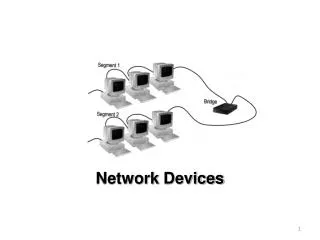
Configuring Network Devices. CCNA Discovery 2: Chapter 5. Contents. 5.1: Router Setup 5.2: SDM 5.3: Router Configuration 5.4: Connecting to the ISP 5.5: Switch Configuration. 5.1: Routers. A router is a specialized computer that connects LANS together, through WAN connections

arnold
Download Presentation

Configuring Network Devices

An Image/Link below is provided (as is) to download presentation Download Policy: Content on the Website is provided to you AS IS for your information and personal use and may not be sold / licensed / shared on other websites without getting consent from its author. Content is provided to you AS IS for your information and personal use only. Download presentation by click this link. While downloading, if for some reason you are not able to download a presentation, the publisher may have deleted the file from their server. During download, if you can't get a presentation, the file might be deleted by the publisher.

E N D

Presentation Transcript


  1. Configuring Network Devices

    CCNA Discovery 2: Chapter 5
  2. Contents 5.1: Router Setup 5.2: SDM 5.3: Router Configuration 5.4: Connecting to the ISP 5.5: Switch Configuration
  3. 5.1: Routers A router is a specialized computer that connects LANS together, through WAN connections Routers are similar to PCs in many ways: They have an operating system: Cisco IOS They use Configuration Files: contain the instructions and parameters that control the flow of traffic in and out of the routers They have the same basic internal hardware components as a PC Routers have 2 specialized functions To determine the best path for data to travel through the connected networks To switch data packets to the correct outgoing interface
  4. Integrated Services Router An ISR Router is a router that combines the functions of routing, LAN switching, security, voice, and WAN connectivity features into one device Optional integrated switch module which allows small businesses to connect LAN devices directly to the 1841 ISR It is ideal for small to medium-sized businesses and for ISP-managed customers.
  5. Physical Router Setup Tools and equipment required for setup:
  6. Router Components
  7. Router Components RAM/DRAM: Random Access Memory Temporary memory that stores the current configuration file of the router Also stores routing tables, ARP cache, and provides packet buffering Loses content when router is powered down or restarted NVRAM: Non-Volatile RAM Permanent memory which stores the saved configuration file Retains content when router is powered down or restarted FLASH: EPROM memory (erasable, programmable ROM) Permanent memory which stores the IOS image file Can store multiple versions of IOS software for easier updates Is a type of electronically erasable, programmable ROM (EEPROM) ROM: Read only memory Permanent memory which contains the BIOS program and instructions for POST Requires replacing pluggable chips on the motherboard for software upgrades Ports/Interfaces: Ports on the router that allows it to connect to a network (either LAN or WAN) or to devices for management purposes
  8. Router Components CPU The microprocessor that executes instructions in the operating system functions are system initialization, routing functions, and network interface control Buses Most routers contain a system bus and a CPU bus The system bus is used for communication between the CPU and the interfaces and/or expansion slots. It transfers the packets to and from the interfaces. The CPU bus is used by the CPU for accessing components from router storage. It transfers instructions and data to or from specified memory addresses. Power Supply The power supply provides the necessary power to operate the internal components.
  9. Router Interfaces Router Interfacesare the connections to the outside world. They provide network connections through which packets enter and exit the router Each interface has its own I/O port Can connect to LANs or WANs Every router has at least 2: 1 LAN and 1 WAN LAN Interfaces: used to connect to a LAN Ethernet LAN interface Ex. E0, FA0, E0/0, E1/0/0 WAN Interfaces: a serial interface which allows connections to another network Provides a connection to ISP service or another router serial, ISDN, and integrated Channel Service Unit (CSUs) interfaces Ex. S0, S1/0, S1/0/1 Management Ports: these allow you to connect to a router to manage and troubleshoot it Console port – allows you to connect to a computer’s com port with a rollover cable and a DB-9 or DB-24 adapter Hyperterminal software is used to establish a console connection Aux port – allows you to connect a modem to the router, and use Telnet to access the router (and hyperterminal)
  10. IOS Cisco Internetwork Operating System (IOS) The operating system used in Cisco network devices is called the IOS Cisco IOS software is offered to customers in modules called images. The entry-level Cisco IOS software image is called the IP Base image. The IP Base image supports small to medium-sized businesses and supports routing between networks. Other Cisco IOS software images add services to the IP Base image.
  11. IOS Images
  12. Router Bootup Process Power-on self test (POST) tests the router hardware After POST, the bootstrap program is loaded The Bootstrap program is loaded from ROm Locate and load Cisco IOS IOS is located from: flash memory (default) a TFTP server Boot into ROMmon Mode IOS is loaded into RAM The IOS locates the hardware and software components and lists the results on the console terminal Locate and execute the startup configuration file or enter setup mode startup configuration file is copied into RAM a prompt containing the host name is displayed Routing processes are started, addresses supplied to interfaces If no configuration file is found, the Router enters Setup mode
  13. Router Bootup 1 2 ROMmon Mode 3 Setup Mode
  14. POST Results
  15. Locate the IOS
  16. Locate the Config File
  17. Bootup Failure There are times when the router does not successfully boot. This failure to boot can be caused by a corrupt or missing Cisco IOS file an incorrect location for the Cisco IOS image specified by the configuration register inadequate memory to load a new IOS image If a router fails to boot the IOS, it then boots up in ROM monitor (ROMmon) mode ROMmon software is a simple command set stored in read only memory (ROM) that can be used to troubleshoot boot errors and recover the router when the IOS is not present.
  18. ROMmon Mode When the router boots up to ROMmon mode, one of the first steps in troubleshooting is to look in flash memory for a valid image rommon 1> dir flash: If an image is located, then you can attempt to boot the image manually rommon 1> boot flash:<IOS filename> Example: rommon 1> boot flash:c2600-is-mz.121-5
  19. Bootup Troubleshooting If the router boots properly from ROMmon mode with the boot command, there are 2 possible reasons why the Cisco IOS image did not load from flash initially An incorrect configuration register setting , which determines the boot sequence for the IOS file Use the show version command to check this setting A configured boot system command which is instructing the router to look in a different location for the Cisco IOS image Use the show startup-configcommand to check for boot system commands
  20. View Boot System Commands
  21. View Configuration Register The show version command can be used to verify the configuration register setting
  22. Methods of Management There are two ways to connect a PC to a router or switch to perform configuration and monitoring tasks: Out-of-band management for initial configuration Uses the console port and a Terminal Emulation program (ex. hyperterminal) to connect a PC to a router or switch for management and configuration In-band management over a network connection Uses a remote management tool like telnet, and a local area network port to manage and configure a router
  23. Out-of-band Management Requires: a direct connection to the console port or auxiliary port (AUX) of the router or switch a terminal emulation client (Hyperterminal) Does not require the local network connections on the device to be active Used for: Initial configuration of a network device, because the device cannot participate in the network until configured When the network connectivity is not functioning correctly and the device cannot be reached over the network.
  24. In-Band Management Requires: at least one network interface on the device must be connected to the network and be operational Telnet, HTTP or SSH can be used to access the device A web browser or a Telnet client program can be used to monitor the network device or make configuration changes Used for: monitoring a device making configuration changes to a device
  25. Methods of Management
  26. Establishing a Hyperterminal Session Connect a rollover cable from the console port on the router to the com port on a PC, using a DB-9 adapter The Console port is EIA/TIA-232 asynchronous serial console port (RJ-45). Start Hyperterminal Program from the PC to establish a connection
  27. Hyperterminal Session Settings
  28. Router Configuration There are 2 types of interfaces that can be used to configure a router: Command Line Interface (CLI) A text-based interface Enables entering and executing Cisco IOS commands to configure, monitor, and maintain Cisco devices Can be used for either in-band or out-of-band management tasks Offers many time-saving features for creating both simple and complex configurations Security Device Manager (SDM) A web-based GUI device management tool Simplifies the initial router configuration Uses a step-by-step approach to create a basic router configuration quickly and easily Can ONLY be used for in-band management tasks Does not support all the CLI commands SDM is available only on later versions of the IOS and recent router models (1841)
  29. Configuration Files The router configuration files contain the commands used to determine how the device operates on the network. Startup Configuration File The permanent, saved configuration file, used to operate the router Stored in NVRAM Running Configuration File The current version of the configuration file, which is held in RAM memory The Running configuration must be saved to NVRAM in order for changes to be permanent Command to save the configuration: Router#copy running-config startup-config Router#copy run start
  30. Best Practices When adding a new device to a network, it is critical to ensure that the device functions correctly. The addition of one poorly configured device can cause an entire network to fail. Configuring a networking device, such as a router, can be a complex task, no matter which tool is used to enter the configuration Always follow best practices for installing a new device to ensure that all device settings are properly configured and documented.
  31. Best Practices for a Router Install
  32. 5.2: Cisco SDM Cisco SDM Express and Cisco SDM can be used to configure a router with a GUI browser-based interface Cisco SDM Express is a tool in SDM that makes it easy to create a basic router configuration SDM has more advanced configuration options After a basic configuration is completed using SDM Express, many users switch to SDM To use SDM Express: Connect an Ethernet cable from the PC’s NIC to the Ethernet port on the router
  33. Cisco SDM Express SDM Express allows you to do a basic router configuration using these 8 screens: Overview Basic configuration Hostame, Passwords LAN Configuration IP Address settings for the LAN interface DHCP Allows you to configure the router as a DHCP server Internet (WAN) Configuration of the WAN interface for connecting to the ISP or to another router Must configure the encapsulation type and the method for obtaining a WAN IP address Firewall Security settings Summary
  34. SMD Express GUI Configuration
  35. SDM WAN Connections A router’s WAN interfaces use a serial connection to connect networks together Router to Router connection or Router to ISP connection Serial connections are lower speed links, than Ethernet links WAN Connection Configuration: The protocol encapsulation must be the same at both ends of a serial connection. Some types require authentication parameters Serial Encapsulation types: High-Level Data Link Control (HDLC) Frame Relay Point-to-Point Protocol (PPP)
  36. WAN Addressing WAN Interface Configuration Involves: Set the Encapsulation Type High-Level Data Link Control (HDLC) Frame Relay Point-to-Point Protocol (PPP) Choose the Address Type – how the serial interface will obtain its WAN IP address Static IP address Supported by Frame Relay, PPP, and HDLC IP unnumbered Sets the serial interface address to match the IP address of one of the other router interfaces Supported by Relay, PPP, and HDLC IP negotiated The router obtains an IP address automatically through PPP Easy IP The router obtains an IP address automatically through PPP
  37. SDM NAT Configuration A router can also be configured as a NAT server with SDM Enables hosts on the internal local network to share a single registered IP address assigned to the WAN interface Not available in the Express version The Basic NAT Wizard configures Dynamic NAT with PAT, by default NAT configuration Involves Step 1. Enable NAT configuration using SDM. Step 2. Navigate through the Basic NAT Wizard. Step 3. Select the interface and set IP ranges. Step 4. Review the configuration.
  38. 5.3: Cisco CLI The Cisco CLI is a text-based interface available on all Cisco devices running an IOS IT enables entering and executing Cisco IOS commands to configure, monitor, and maintain Cisco devices Can be used for either in-band or out-of-band management tasks Offers many time-saving features for creating both simple and complex configurations
  39. 5.3: CLI Access There are 2 main levels of access to the CLI: User EXEC mode Privileged EXEC mode Both modes can be protected with a password, or a username and password combination.
  40. CLI Modes Various modes are available in the router IOS, and each is used for a different purpose: User mode for limited viewing of status Privileged exec mode view status, troubleshooting, configuring Type enable to enter this mode Global configuration mode Configuring general router parameters Type config t to enter this mode Interface configuration mode Configuring LAN and WAN interfaces Type Int [interface name] to enter this mode Router configuration mode Configuring routing protocols Type router [routing protocol] to enter this mode Line configuration mode Configuring port parameters, for console and telnet sessions Type line [line type] to enter this mode
  41. Router Modes User Mode Password:cisco Router>enable Router#config t Router (config)# router rip line con 0 ints0 Router Config Mode Line config Mode Interface Config Mode Router(config-router#) Router(config-line#) Router(config-if#) ctrl Z Exit Privileged Exec Mode Global ConfigMode
  42. User Exec Mode The router boots into this mode by Default Indicated by the prompt: Router> Used for viewing information about how the device is operating, and limited troubleshooting
  43. Privileged Exec Mode Used to enter commands that can alter the operation of the device You can change into privileged EXEC mode by using the enable command Router> enable Indicated by the prompt Router# To disable the privileged mode and return to user mode, enter the disable command Router# disable
  44. Global Configuration Mode Allows you to change the configuration of a router Can enter simple configuration commands like assigning a name to the router, setting a message of the day, and assigning hostnames to the routers Enter Configure Terminalor config t to get to global config mode Router# config t Router(config)#
  45. Router configuration Mode Allows you to set up routing protocols on the router Type router rip or router igrp to get into router config mode Router(config)# router rip Router(config-router)#
  46. Line config Mode Allows you to configure passwords for the console connection, the 5 telnet session lines, and the auxillary line for an outside modem connection Enter the name of a line to get to this mode: ex. Line con 0 or line vty 0 4 Router(config)# line con 0 Router(config-line)#
  47. Interface config mode Allows you to set things like IP addresses and subnet masks for interfaces Enter the name of an interface to get to this mode: ex. int s0 Router(config)# int serial 0 Router(config-if)#
  48. CLI Modes
  49. Using the CLI Help
  50. Error Messages
  51. Showing a list of available commands: ?
  52. Using the Command history
  53. Show Commands Show commands display important information about the configuration and operation of the device Network technicians use the show commands extensively for viewing configuration files, checking the status of device interfaces and processes, and verifying the device operational status. Show commands are available whether the device was configured using the CLI or SDM. The status of nearly every process or function of the router can be displayed using a show command: show running-config show interfaces show arp show ip route show protocols show version
  54. Show Run Shows the contents of the running configuration file Use to check a configuration after it has been completed and to troubleshoot a router Includes: Hostname Passwords Interface addressing Routing protocols DNS host entries Static Routes Default Routes
  55. Show Interfaces Shows the status of all of the Router Interfaces Can use to troubleshoot Interface connections Includes: Status of interface (up/down) Packet information
  56. Show Arp Shows table of MAC to IP Address mappings that the router has learned
  57. Show IP Route Shows the contents of the routing table Shows networks (routes) that the router knows about, including default and static routes Also shows how the routes were learned
  58. Show IP Protocols Shows information about Routing Protocols that have been configured
  59. Show Version Shows information about the Router hardware and software Also shows the setting of the configuration-register (which determines how the router boots)
  60. Basic Router Configuration A Basic Router configuration includes: Assign the device a name: Hostname Set the password for accessing privileged mode Configure Banner messages Set passwords for console and telnet connections to the router Configure Interfaces with IP addressing information and enable them Configure a default route so the router can find other routers Configure DNS host name entries for the DNS table Configure parameters to simply working in the CLI – password encryption, disable DSN lookup, turn off status messaging Verify the configuration Save the configuration
  61. Hostname and Password Configure a device name Router (config)# hostname [name] Router (config)# hostname NewYork Configure passwords for router access Router (config) # enable password [password] Router (config) # enable password cisco Router (config) # enable secret [password] Router (config) # enable secret class Enable password: a password for privileged mode that’s not encrypted Enable secret: a password for privileged mode that is encrypted
  62. Basic Configuration
  63. Banners A banner is text that a user sees when initially logging on to the router. Configuring an appropriate banner is part of a good security plan. At a very minimum, a banner should warn against unauthorized access. There are two types of banners: message-of-the-day (MOTD) Login information Configure Banners Router (config) # banner motd #hello# Router (config) # banner login #welcome# A delimiting character, #, is used at the beginning and at the end of the message. If both banners are configured, the login banner appears after the MOTD but before the login credentials.
  64. Console and Telnet ports There are multiple ways to access a device to perform configuration tasks Console connection A PC attached to the console port on the device Vty connection A telnet connection through the network Setting a password for console and telnet connection access prevents unauthorized users from accessing user mode from the console port or a telnet session
  65. Console Port Configuration A console connection is frequently used for initial device configuration. The console port is named console 0 Console Port Configuration Router(config)# line console 0 Router(config)# password [password] Router(config)# login
  66. Vty Port Configuration When a device is accessed through the network (with telnet), it is considered a vty connection 5 telnet sessions are supported at a time, so there are 5 vty ports: vty 0 through vty 4 You can configure each one separately, or all 5 at once Telnet Port (vty port) Configuration Router(config)# line vty 0 4 Router(config)# password [password] Router(config)# login
  67. Router Interfaces To direct traffic from one network to another, router interfaces are configured to participate in each of the networks A router interface connecting to a network must have an IP address and subnet mask that is within the host range for the connected network or subnet There are different types of interfaces on a router. Serial and Ethernet interfaces are the most common.
  68. Interface Types Local network connections use Ethernet interfaces. WAN connections require a serial interface, which connects to an ISP device serial interfaces require a clock signal to control the timing of the communications, called a clock rate. In most environments, data communications equipment (DCE) devices, such as a modem or CSU/DSU, provide the clock rate
  69. WAN Interface Connections A serial interface on a router provides a WAN connection to the ISP. There are different ways the router can connect to the ISP WAN network DCE Devices The ISP equipment that provides the clocking rate for the serial communication over the WAN link a CSU/DSU is used if the WAN is digital. A modem is used if the WAN is analog These devices convert the data from the router into a form acceptable for crossing the WAN, and convert data from the WAN into an acceptable format for the router. DTE Devices Routers are considered data terminal equipment (DTE) devices, because they accept the clock rate from the DCE device When 2 routers are directly connected, a back to back serial cable with a DCE end and a DTE end is used. The serial interface connected to the DCE end of the cable is configured with a clock rate for timing.
  70. Interface Configuration Step 1: Specify the type of interface and the port number. Step 2: Set a description of the interface. Step 3: Configure the IP address and subnet mask. Step 4: Set the clock rate, if configuring a serial interface as a DCE. Step 5: Enable the interface.
  71. Ethernet Interface configuration Specify the type of interface and the port number Router(config)#interface E0 Set a description of the interface Router(config-if)#description NY LAN Configure the IP address and subnet mask Router(config-if)#ip add 192.168.14.1 255.255.255.0 Enable the interface Router(config-if)#no shutdown
  72. Serial Interface configuration Specify the type of interface and the port number Router(config)#interface S0/1 Set a description of the interface Router(config-if)#description NY LAN Configure the IP address and subnet mask Router(config-if)#ip add 192.168.14.1 255.255.255.0 Set the clockrate on the DCE interface Router(config-if)#clockrate 56000 Enable the interface Router(config-if)#no shutdown
  73. Interface Naming There are many different types of routers, so there are different ways to indicate interfaces The naming of an interface depends on wether it is: A router with Built-in interfaces A Modular Router with interface cards A router with multiple controllers for interface cards Non-Modular Routers use the designation: Port # Example: Serial0, Ethernet1, FA2 (fast ethernet) Modular Routers use the format C/S/P or C/P C=Controller# S=Slot# P=Port# Examples: Serial 1/0 Serial0/0/0 E1/1 FA0/1/2
  74. Configuring Interfaces
  75. Default Route A router forwards packets from one network to another based on the destination IP address specified in the packet. It examines the routing table to determine where to forward the packet to reach the destination network. If the router does not have a route to a specific network in its routing table, a default route can be configured to tell the router how to forward the packet. The default route is the IP address where packets leaving the LAN are sent when the router does not know where to send a packet. Usually, the default route points to the next hop router on the path to the Internet. The IP address of the next hop router must be configured on the router as the default route
  76. Configure a Default Route Syntax: Router(config)# ip route 0.0.0.0 0.0.0.0 [next-hop-IP-address] Example: Router(config)# ip route 0.0.0.0 0.0.0.0 200.10.1.1 The 0.0.0.0 0.0.0.0 indicates that all destination networks will match, so send all packets leaving the LAN to this address
  77. DNS Host Entries The router keeps a DNS host name table to allow you to use the hostname of a device, instead of IP addresses, when trying to communicate with other devices. You can Ping or telnet to a router’s Hostname, if you have entered it into your router’s DNS host table Syntax: Router(config)# ip host [hostname] [ip addresses of all interfaces on that host] Configuration of DNS Host entry Router(config)# ip host LA 192.168.15.2 192.168.16.1
  78. CLI management commands Synchronous Logging The IOS software often sends unsolicited messages, like an interface status message, which can interrupt your commands Disable status commands Router (config) # synchronous logging Disabling Domain Lookup When a host name is entered in enable mode, the router assumes that the user is attempting to telnet to a device. The router tries to resolve unknown commands entered in enable mode by sending them to the DNS server Disable DNS Lookup Router (config) # no ip domain-lookup
  79. CLI management commands Password Encryption Unless you use the command service password-encryption, passwords other than the enable secret, are stored in the running-configuration in clear text. You can verify passwords with the show running-configcommand. Configure password encryption Router# show running-config Router# service password-encryption
  80. Router Configuration Summary Enter into Privileged Exec mode Router> Enable Enter into Global Configuration Mode Router # Configure terminal Configure Hostname Router(config)#hostname [name] Configure Password for privileged exec mode Router(config)#enable password [password] OR Router(config)#enable secret [password] enable password is not encrypted by default Configure Banners Router(config)#banner motd Router (config)#banner login
  81. Router Configuration Summary Configure Passwords for Console and Telnet connections Router(config)# line console 0 Router(config)# password [password] Router(config)# login Router(config)# line vty 0 4 Router(config)# password [password] Router(config)# login
  82. Router Configuration Summary Configure Interfaces Router(config)#interface S0/1 Router(config-if)#description NY LAN Router(config-if)#ip add 192.168.14.1 255.255.255.0 Router(config-if)#clockrate 56000 Router(config-if)#no shutdown Configure a Default Route Router(config)# ip route 0.0.0.0 0.0.0.0 200.10.1.1 Configure Host name entries for DNS table Router(config)#ip host NY 192.168.1.1 192.168.2.1 192.168.3.2
  83. Router Configuration Summary Configure CLI Administrative Tasks Password Encryption Router(config)# service password-encryption Turn off unwanted messages Router(config)# logging synchronous Disable DNS lookup Router(config)# no ip domain-lookup Back out of config mode Router(config-line)#ctrl z Check your configuration Router#show run Save the configuration Router#copy run start
  84. Testing To verify that your network is up and running, do each of the following: Show Interfaces:Make sure each interface shows a message like: “Serial 0 is up, Line Protocol is up” Ping a host on your LAN Ping the Hostname of any routers connected to you, to test your DNS table If you can NOT Ping a Router with it’s hostname, then Ping each interface on the router connected to you, to make sure it is receiving packets and narrow down the problem Telnet to each router connected to you, using it’s hostname
  85. Important Router Commands Enable: to enter privileged exec mode Config t: enter into global config mode Exit:back out 1 CLI mode level at a time Ctrl Z : back all the way out to privileged exec mode Erase start: erases the startup config Reload: reboots the router Show run: check the running config Show interface: shows interface status
  86. Tftp Backup of configuration It is a good idea to save a router’s configuration file in another location, such as a network server or tftp server A tftp server uses Trivial File Transfer Protocol to transfer files between devices over a network connection The TFTP server and router must be able to communicate through a LAN connection To Perform a tftp Backup: Step 1: Enter the copy startup-configtftpcommand. Step 2: Enter the IP addressof the TFTP server where the configuration file will be stored. Step 3: Enter the filename to assign to the configuration file or accept the default. Step 4: Confirm each choice by answering yes.
  87. Restore a backup with tftp To restore the backup configuration file, the router must have at least one interface configured and be able to access the TFTP server over the network. Step 1: Enter the copy tftp running-config command. Step 2: Enter the IP address of the tftp server where the config file is stored Step 3: Enter the name of the configuration file or accept the default name. Step 4: Confirm the configuration filename and the TFTP server address. Step 5: Use the copy run start command to copy the running-configuration to the startup-configuration file to save it it is also possible to copy the tftp file to the startup configuration file. this requires a router reboot in order to load the startup configuration file into the running configuration.
  88. Using tftp for Backups TftpConfigurationbackup. Tftp Configuration Restore
  89. Save a Configuration File as Text Another way to create a backup copy of the configuration is to capture the output of the show running-config command as a Text file. To do this from the terminal session you can use the Capture Text function To capture the configuration from a HyperTerminal screen. Step 1. Select Transfer > Capture Text Step 2. Specify a name for the text file to capture the configuration. Step 3. Select Start to start capturing text. Step 4. Type the show running-configcommand to display the configuration on the screen. Step 6. Press the spacebar when each "-More -" prompt appears. Step 7. After the complete configuration has been displayed, Select Transfer > Capture Text > Select Stop Edit the Text file: The configuration file must be edited to remove extra text and add a few Remove: Extra messages: "building configuration“ -More- Messages Any extra symbols, ex. ------ or !!!!!! Add: the no shutdown command to the end of each interface section.
  90. Restore a Configuration from a saved Text File The saved text configuration file can also be restored from a HyperTerminal session. Before the configuration is restored, you must: Erase the current configuration: erase startup-config Reboot the router: reload Restore a saved Config File Step 1: Enter router global configuration mode. Step 2: Select Transfer > Send Text File in HyperTerminal. Step 3: Select the name of the file Step 4: Save the configuration with the copy run start command
  91. Save Configuration File as Text
  92. Configure DHCP The Cisco IOS CLI can be used to configure a router to function as a DHCP server. Using a router configured with DHCP simplifies the management of IP addresses on a network.
  93. Configure DHCP Step 1: Create a DHCP address pool. Step 2: Specify the network or subnet. Step 3: Exclude specific IP addresses Exclude static addresses that will be used for router interface and servers Step 4: Specify the domain name. Step 5: Specify the IP address of the DNS server. Step 6: Set the default gateway. Step 7: Set the lease duration. Step 8: Verify the configuration.
  94. Step 1: Create DHCP Address Pool
  95. Step 2: Specify the Network Address
  96. Step 3: Specify addresses to exclude
  97. Step 4: Set Domain Name
  98. Step 5: Set DNS Server Address
  99. Step 6: Set Default Gateway
  100. Step 7: Set the Lease Time
  101. Step 8: Verify You can use the show running-configcommand to verify the DHCP settings
  102. Configure NAT NAT enables hosts with internal private addresses to communicate on the Internet. The Interface connected to the Internal LAN is configured as the inside interface. The External Interface, connected to the Internet, is configured as the outside interface When devices on the internal network communicate out through the external interface, the addresses are translated to one or more registered IP addresses. Static NAT allows a server located on the internal network to be accessible from the Internet. The server must have a specific registered address that external users can specify. Static NAT ensures that addresses assigned to hosts on the internal network are always translated to the same registered IP address.
  103. Configuring Static NAT Step 1: Specify the inside interface to use. Step 2: Set the primary IP address of the inside interface. Step 3: Identify the inside interface using the ipnat inside command. Step 4: Specify the outside interface to use. Step 5: Set the primary IP address of the outside interface. Step 6: Identify the outside interface using the ipnat outside command. Step 7: Define the static address translation. Step 8: Verify the configuration.
  104. Step 1: Specify Inside Interface
  105. Step 2: Set IP Address of Inside Interface
  106. Step 3: Identify interface as Inside
  107. Step 4: Specify Outside Interface
  108. Step 5: Set IP Address for Outside Interface
  109. Step 6: Identify the Interface as Outside
  110. Step 7: Define a Static NAT address translation Inside Address Outside Address
  111. Step 8: Verify There are several router CLI commands to view NAT operations for verification and troubleshooting. show ipnat translations shows static and dynamic NAT translations displays the detailed NAT assignments show ipnat statistics displays information about the total number of active translations, NAT configuration parameters, how many addresses are in the pool, and how many have been allocated. show run view NAT configurations clear ipnat translation * To clear dynamic entries before the timeout has expired
  112. 5.4: Installing CPE One of the main responsibilities of an on-site network is to install and upgrade equipment located at a customer home or business. Network devices installed at the customer location are called customer premises equipment (CPE): Routers, Modems, and Switches The installation or upgrade of a router can be disruptive for a business. New equipment is typically configured and tested at the ISP site before being installed at the customer site
  113. Planning CPE Installs Planning the installation or upgrade of CPE is a critical step in ensuring successful operation: Determine the configuration of the router to meet customer needs Determine network software that may be affected by the new installation or upgrade Develop a procedure to verify the router configuration Complete a configuration checklist
  114. Configuration Checklist The configuration checklist provides a list of the most commonly configured components. It includes an explanation of each component and the configuration setting
  115. Installing CPE Use inventory and configuration checklists and an installation plan to ensure successful installation
  116. Connecting the CPE to the ISP Complete the job in a professional manner: Network cables are labeled and fastened together or run through proper cable management equipment Excess lengths of cable are coiled and secured out of the way Documentation should be updated Network diagrams should be updated to show the location of the equipment and cables installed Installation Checklist if verified by the Employer
  117. WANs and TSPs WANs: Wide Area networks that connect LANs in geographically separated locations TSP : Telecommunications service provider network large regional networks that can span long distances used to interconnect LANs that are geographically separated Connections are leased by organizations ISPs sell various types of WAN connections to their clients
  118. Types of WAN connections WAN connections vary in: type of connector used Bandwidth cost Types of serial WAN connections through ISP: Point-to-point Circuit-switched Packet-switched
  119. PPP A predefined communications path from the customer premises through a TSP network A dedicated circuit with fixed bandwidth available at all time A Leased Line from the TSP Most expensive type prices based on the bandwidth required and the distance between the two connected points Ex. T1 or E1 link
  120. Circuit-Switched Functions similarly to the way a phone call is made over a telephone network A connection, or circuit, is made only when needed, and then closed when the communication is complete Examples: ISDN Dialup connection
  121. Circuit-Switched
  122. Packet Switched Many customer networks have connections into the TSP switched network Each customer has its own virtual circuit A logical path between the sender and receiver, not a physical path. Example: Frame Relay
  123. Packet Switched
  124. Choosing a WAN connection Bandwidth and costare the main factors influencing WAN choices
  125. Configuring WAN connections How a WAN is configured depends on the type of WAN connection required Leased-lines: Use a serial connection Use a channel service unit/data service unit (CSU/DSU) to attach to the ISP network 2 Configurations must be made for a Serial WAN connection: clock rate set by the DCE device, which is typically the CSU/DSU. DTE device, typically the router, accepts the clock rate set by the DCE Serial Encapsulation Type Cisco default serial encapsulation is HDLC
  126. Configuring WAN connections
  127. 5.5: LAN Switches A LAN switch is a device that directs traffic between network segments Frames are forwarded between switch ports based on their destination MAC address A switch cannot route traffic between two different local network segments A switch performs Layer 2 functions (Data Link Layer)
  128. Types of Switches
  129. Communication Modes Switch ports support 2 methods of communication: Half-duplex mode A host on that port can either send or receive data but not both at the same time Full-duplex mode A host on that port can simultaneously send and receive data, doubling the throughput Both the port and the connected device must be set to the same duplex mode If they are not the same, a duplex mismatch occurs, which can lead to excessive collisions and degraded communication
  130. Autonegotiation The speed and duplex can be set manually, or the switch port can use autonegotiation Allows the switch to auto-detect the speed and duplex of the device that is connected to the port Enabled by default on many Cisco switches Both devices must support autonegotiation If the switch is in autonegotiation mode and the connected device does not support it, the switch uses the speed of the other device (10, 100, or 1000) and is automatically set to half-duplex mode
  131. New Switch Install Check switch components Connect cables to the switch Power up the switch and observe POST POST is completed when the SYST LED rapidly blinks green If the switch fails POST, the SYST LED turns amber.
  132. Switch Configuration There are several ways to configure and manage a Cisco LAN switch: Cisco Network Assistant Cisco Device Manager Cisco IOS CLI CiscoView Management Software SNMP Network Management Products Some of these methods use IP connectivity or a web browser to connect to the switch, which requires an IP address. Unlike router interfaces, switch ports are not assigned IP addresses. use an IP-based management product or Telnet session to manage a Cisco switch, it is necessary to configure a management IP address on the switch. If the switch does not have an IP address, it is necessary to connect directly to the console port and use a terminal emulation program to perform configuration tasks.
  133. Management IP Address Switch Ports are not assigned IP Addresses To use an IP-based management product or Telnet with a Cisco switch, you must configure a management IP address. To assign an address to a switch, the address must be assigned to a virtual local area network (VLAN) interface A VLAN allows multiple physical ports to be grouped together logically By default, there is one VLAN, preconfigured in the switch, VLAN1, that provides access to management functions.
  134. Switch Configuration Configure a hostname Configure a privileged mode Password Configure Console and Telnet passwords Configure Banners Enable Password Encryption Configure the Default gateway Switch(config)# ip default-gateway 192.168.1.1 Configure a management IP address on VLAN 1 Switch(config)# interface vlan 1 Switch(config-if)# ip address 192.168.1.2 255.255.255.0 Save the Configuration Switch# Copy run start
  135. Switch Configuration
  136. Connect the Switch to a Router To connect the switch to a router, use a straight-through cable Verify that VLAN1 and the router are on the same network with show run Test the connection by pinging the default gateway Connect PCs to the switch with straight-through cables
  137. Port Security Switch ports can be an unwanted entry point to the network by unauthorized users To prevent this, switches provide a feature called port security Limits the number of valid MAC addresses allowed per port The port will ONLY forward packets for source MAC addresses that are defined in the security settings There are 3 ways to configure port security. Static Dynamic Sticky
  138. Static Port Security Static Port Security: MAC addresses that are allowed to connect to the port are manually assigned Static MAC addresses are stored in the address table and added to the running configuration Configuration: Switch(config)# interface fa 0/5 Switch(config-if)# switchport mode access Switch(config-if)# switchport port-security <MAC address>
  139. Dynamic Port Security Dynamic Port Security: MAC addresses that are allowed to connect to the port are dynamically learned and stored in the address table The maximum number of addresses learned can be controlled By default, the maximum is 1 MAC Addresses are only temporarily stored in the table and in RAM – if the switch is restarted, they are dumped Configuration: Switch(config)# interface fa 0/5 Switch(config-if)# switchport mode access Switch(config-if)# switchport port-security
  140. Sticky Port Security Sticky Port Security: MAC addresses that are allowed on the port are learned dynamically, but then they are saved to the running config file Once the maximum # of MAC addresses is reached, the port will shut down The learned addresses are stored in the table and the running config file permanently Configuration Switch(config)# interface fa 0/5 Switch(config-if)# switchport mode access Switch(config-if)# switchport port-security Switch(config-if)# switchport port-security maximum 5 Switch(config-if)# switchport port-security mac-address sticky
  141. Security Violations Port security is disabled by default on a Cisco switch Before port security can be activated, the port must be set to access mode If port security is enabled, a violation will result in the port being shutdown A security violation occurs when: The max number of secure MAC addresses has been added to the address table, and another device attempts to access the interface. An address learned or configured on one secure interface is seen on another secure interface in the same VLAN Example: If dynamic port security is enabled and the maximum number of MAC addresses per port is one, the first address learned becomes the secure address If another workstation attempts to access the port with a different MAC address, a security violation occurs. The port will shut down
  142. Verify Port Security Switch# show port-security interface fa 0/2 Shows maximum allowed number of secure MAC addresses for that interface Shows number of secure MAC addresses on the interface Shows number of security violations that have occurred on that port Shows the violation mode Switch# show port-security address displays the secure MAC addresses for all ports Includes static, dynamic and sticky Switch# show port-security displays the port security settings for the switch
  143. Clearing Sticky Port Security Switch#show running-config Displays the MAC address associated with a specific port when using sticky port security 3 Ways to clear learned MAC Addresses Clear sticky addresses Switch(config-if)# clear port-security sticky interface fa 0/2 access Shutdown the port (Switch(config-if)#shutdown) Re-enable the port (Switch(config-if)# no shutdown) Disable port security and then Re-enable Switch(config-if)# no switchport port-security Switch(config-if)# switchport port-security Reboot the switch
  144. Disabled Ports If there are any ports on a switch that are unused, the best practice is to disable them
  145. Cisco Discovery Protocol Cisco Discovery Protocol (CDP) is an information-gathering tool used on a switch, ISR, or router to share information with other directly connected Cisco devices. By default, CDP begins running when the device boots up. It then sends periodic messages, known as CDP advertisements, to any directly connected networks. CDP operates at Layer 2 only and can be used on many different types of local networks, including Ethernet and serial networks. It can be used to determine the status of a directly connected link when no IP address has been configured, or if the IP address is incorrect. Viewing CDP information does not require logging in to the remote devices.
  146. CDP Neighbors Two Cisco devices that are directly connected on the same local network are referred to as being neighbors. The concept of neighbor devices is important to understand when interpreting the output of CDP commands. Information gathered by CDP includes: Device identifiers - Configured host name Address list - Layer 3 address, if configured Local Interface – The port on the current router or switch that the neighbor device is connected to Port identifier – The port on the neighbor device that is connected to your device; for example, serial 0/0/0 Capabilities list - Function or functions provided by the device Platform - Hardware platform of the device; for example, Cisco 1841
  147. Enabling/Disabling CDP Disable CDP on the entire router or switch Disable CDP on just 1 interface If CDP is disabled globally, to re-enable it you must: Enable it globally (Router(config)# cdp run) Enable it on each interface (Router(config)# cdp enable)
  148. Viewing CDP Information Router# show cdp neighbors Shows a summary for each directly connected device Includes: Device name Local interface – the Interface it’s connected to Hardware platform Device capabilities Port ID - the port it is using to connect to your device Router# show cdp neighbors detail Shows more in-depth details about each device Includes: IP Address of the device’s connected port (if it’s configured) IOS software version
  149. Show cdp neighbors
More Related