Download
1 / 23
230 likes | 373 Views
S2E in LCLS Linac M. Borland, Lyncean Technologies, P. Emma, C. Limborg, SLAC. LCLS. 150 MeV z 0.83 mm 0.10 %. 250 MeV z 0.19 mm 1.8 %. 4.54 GeV z 0.022 mm 0.76 %. 14.35 GeV z 0.022 mm 0.01 %. 6 MeV z 0.83 mm 0.1 %.

E N D
S2E in LCLS Linac M. Borland, Lyncean Technologies, P. Emma, C. Limborg, SLAC
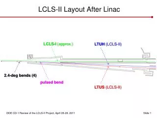
LCLS 150 MeV z 0.83 mm 0.10 % 250 MeV z 0.19 mm 1.8 % 4.54 GeV z 0.022 mm 0.76 % 14.35 GeV z 0.022 mm 0.01 % 6 MeV z 0.83 mm 0.1 % Lh L =0.6 m rf=180 rf gun L0 L = 9 m rf = -38° L = 330 m rf = -43° L = 550 m rf = -10° L = 6 m undulator L = 120 m L1 L2 L3 X ...existing linac BC-1 L = 6 m R56= -36 mm BC-2 L = 22 m R56= -22 mm DL-1 R56 0 DL-2 R56 = 0
LCLS LCLS Start-to-End Tracking Simulations • Track entire machine to evaluate beam brightness & FEL • Track machine many times with jitter to test stability budget • See C. Limborg talk for injector • See Fawley, Reiche talks for FEL Parmela Elegant Genesis space-charge compression, wakes, CSR, … SASE FEL with wakes
Initial Beam from Parmela Tracking • 1 nC • 10-psec FWHM • 0.7-ps rise/fall • 120 MV/m gun • getherm 0.3 mm • 150 MeV gex gex,y < 1 mm gey 2105 to 2106 macro-particles z, DE/E x, y
Sliced e- Beam to Evaluate FEL (Dz 0.7 mm) gex,y sE/E Ipk
centroid match FEL wavelength b mismatch variation slice 4D centroid osc. amplitude
FEL parameter gain length FEL power ‘Ming Xie method’ see S. Reiche, B. Fawley talks…
LCLS Longitudinal Jitter Tolerance Budget LCLS. note, Elegant simulations use 0.5 ps rms X- X-band
DsE/sE0 0.01% DE/E0 0.1% 2D tracking used to develop tolerance budget DI/I0 8.6% Dtfw/tfw 12.5% Dtrms 125 fs Dsz/sz0 12.5%
Now add component transverse misalignments… • Misaligned randomly in x and y: • All quadrupoles: 300 mm rms • All rf structures: 300 mm rms • All BPMs: 300 mm rms Transverse wakefields induce projected emittance growth and couple charge jitter to emittance jitter
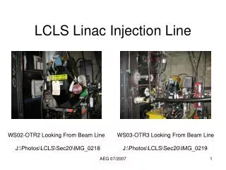
trajectory before steering gex 10000 mm x-y screen • Misaligned randomly in x and y: • All quadrupoles: 300 mm rms • All rf structures: 300 mm rms • All BPMs: 300 mm rms
trajectory after steering Steered using Elegant’s ‘global’ algorithm gex 5 mm gey 2 mm after
after steering coils Now let Elegant optimize both x and y emittances with two x- and two y-steering coils (pairs separated by Dyp/2) gex 1.02 mm gey 1.09 mm
M. Borland optimized 100 random seeds… De/e 20% (projected)
gex (mm) x-position of feedback set-point (mm) Real Emittance Minimization Using Trajectory ‘Bumps’ in SPPS H. Schlarb, P. Emma ~10 minutes (Ne 3.5 nC, sz 1 mm)
Now run 200 S2E simulations, including Genesis runs, but with a distorted and ‘emittance-tuned’ trajectory… M. Borland, PE, J. Lewellen, C. Limborg, M. Woodley SC-wiggler is ON
I 3.91 kA, rms 10% gex 2.29 mm, rms 5% projected x-emittance peak current gey 0.93 mm, rms 4% E 14.36 GeV, rms 0.04% projected y-emittance e- energy
Dt 0, rms 49 fs gexs 0.76 mm, rms 2% sliced x-emittance bunch arrival time geys 0.67 mm, rms 2% sE/E 710-5, rms 0.810-5 sliced y-emittance sliced energy spread
x 0, rms 9 mm (30% sx) x 0, rms 0.55 mrad x-position mean values set to zero for Genesis runs x-angle y 0, rms 1.5 mm y 0, rms 0.21 mrad y-position y-angle
Lg 4.1 m, rms 5% lr 1.5 Å, rms 0.09% Gain length wavelength Lg ? m, rms 5% P 4 GW, rms 25% ??? gain length
Final Comments* • Fairly realistic simulations with jitter demonstrate tight, but achievable tolerances – SPPS experience very helpful • Transverse wakefields are correctable – not a major issue (lower charge, shorter linac, and shorter bunch vs. SLC) • LCLS still deciding on SC-wiggler at BC2, or laser system at injector (as proposed at DESY for TTF-2; Saldin et al.) • LCLS entering engineering stage – detailed design must be ‘nailed’ down very soon (CD-2b in March 2004) * Special thanks to M. Borland: working for free!
CSR gain (1D-model) in LCLS without wakefield or long. space-charge SC-wig OFF SC-wig ON initial modulation period prior to BC1 see Z. Huang talk Tuesday