Download
1 / 34
340 likes | 343 Views
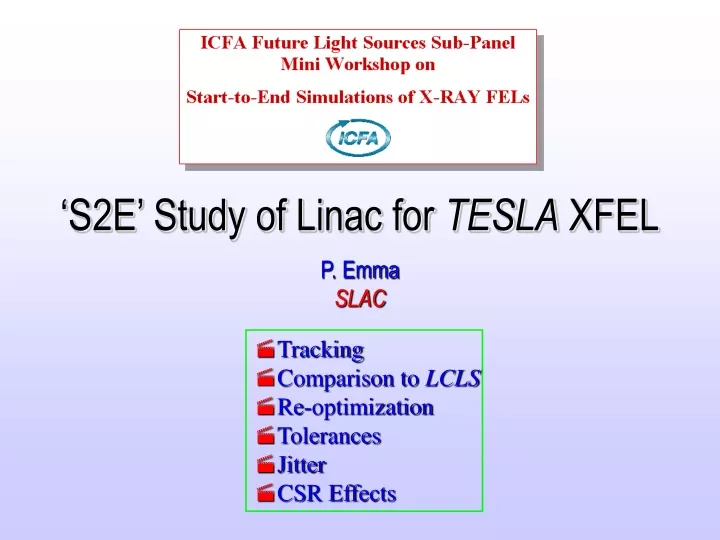
This study focuses on analyzing the linac for TESLA XFEL, including tracking, comparing it to LCLS, re-optimizing its parameters, studying tolerances, investigating jitter, and examining the effects of CSR.

E N D
‘S2E’ Study of Linac for TESLA XFEL P. Emma SLAC • Tracking • Comparison to LCLS • Re-optimization • Tolerances • Jitter • CSR Effects
LCLS rf gun 150 MeV z 0.83 mm 0.10 % 250 MeV z 0.19 mm 1.8 % 4.54 GeV z 0.022 mm 0.76 % 14.35 GeV z 0.022 mm 0.01 % 6 MeV z 0.83 mm 0.1 % Lh L =0.6 m rf=180 rf gun L0 L = 9 m rf = -38° L = 330 m rf = -43° L = 550 m rf = -10° L = 6 m undulator L =120 m L1 L2 L3 X ...existing linac BC-1 L = 6 m R56= -36 mm BC-2 L = 22 m R56= -22 mm DL-1 R56 0 DL-2 R56 = 0 TESLA-XFEL 375 MeV z 0.1 mm 1.4 % 1.64 GeV z 0.020 mm 0.5 % 20.5 GeV z 0.020 mm 0.01 % 6 MeV z 2.0 mm 0.1 % 120 MeV z 0.5 mm 2.0 % Lh L 1.4 m rf= -191 L 72 m rf -40° L 16 m rf -40° L 850 m rf = 0° L = 8 m rf -22° undulator L =? m L0 L2 L3 3.9 L1 BC-1 L 4 m R56= -76 mm BC-2 L 14 m R56= -36 mm BC-3 L 18 m R56= -11 mm (parameters only approximate)
Twiss parameters along TESLA-XFEL undulator BC1 BC2 BC3
BC1+ BC3+ BC2+ m-bunching exaggerated by noise, but gain may be large (see modulated beam study below).
Longitudinal phase space at end of TESLA-XFEL m-bunching exaggerated by noise (see modulation study below) gex 1.3 3.6 mm
Slice energy spread at end of TESLA-XFEL sE/E < 0.01%
Sliced Bunch Analysis gex,y Ipk sE/E0 Dl/l slice 4D centroid osc. amplitude Twiss slice mismatch amplitude
1 mm Quad alignment tolerances 10 mrad Quad roll-angle tolerances
Longitudinal-only simulation with LiTrack (200k in 66 seconds) no CSR
Test rf phase sensitivity: Df0 = 0 Ipk 11 kA Df0 = 0.2° Ipk 6 kA
Scan gun-laser timing and charge, monitoring energy and peak current |Dti| < 0.13 ps |DQ/Q| < 4% |DIpk/Ipk| < 12% gun-timing charge |DE/E| < 0.1% gun-timing charge
gun-timing charge L0-phase L0-voltage |Dti|< 0.13 ps |DQ/Q|< 4% |DV0/V0|< 0.08% |Df0|< 0.07° 3.9-phase 3.9-voltage L1-phase L1-voltage |Dfh|< 0.05° |DVh/Vh|< 0.3% |Df1|< 0.05° |DV1/V1|< 0.21%
|DV2/V2|< 1.6% |Df2|< 1.1° |DV3/V3|< 0.1% |Df3|< 2.2° L2-phase L2-voltage L3-phase L3-voltage System is very sensitive with large 11-kA spike at head (T. Limberg)… Note 2nd-order chirp after BC2 This suggests an increase of the 3.9-GHz voltage
LiTrack with 3.9-GHz voltage raised from 16.6 MV to 21.0 MV previous distribution no spikes
With 21-MV 3.9-GHz rf, again testing rf phase sensitivity: Df0 = 0 Ipk 5.5 kA Df0 = 0.2° …much less sensitive Ipk 4.5 kA
gun-timing charge L0 phase L0 voltage |DV0/V0|< 0.20% |Df0|< 0.09° |Dti|< 6.0 ps |DQ/Q|< 100% 3.9-phase 3.9-voltage L1 phase L1 voltage |Dfh|< 0.19° |Df1|< 0.24° |DV1/V1|< 1.0% |DVh/Vh|< 1.0%
|Df3|< 2.2° |DV3/V3|< 0.1% L3 phase L3 voltage L2 phase L2 voltage |Df2|< 0.49° |DV2/V2|< 1.4%
adjusted 3.9-GHz original 3.9-GHz & X-band
Form ‘jitter budget’ based on uncorrelated jitter: h- 3.9-GHz & X-band degrees of X-band or 3.9-GHz
LiTrack Jitter Simulation of TESLA-XFEL using ‘jitter budget’ energy • (DE/E0)rms • 0.09% Dl/l • 0.18% energy spread 6.7 minutes @ 5 Hz (no CSR) (DI/I0)rms 13% peak current (Dt)rms 0.2 ps arrival time
Now test re-optimized setup with full 6D tracking (Elegant) No CSR
Elegant tracking with CSR (and increased 3.9-GHz voltage) 4 keV injector slice energy spread m-bunching exaggerated by noise, but gain at l 3 mm may be large (see modulation study below) gex 1.3 2.4 mm
Elegant tracking with CSR and slice energy spread ×6 from gun 23 keV injector slice energy spread gex 1.3 2.0 mm m-bunching damped by large intrinsic energy spread (23 keV or 10-4 at undulator)
Full 6D Elegant tracking with increased 3.9-GHz voltage and “23 keV” slice ge slice sE/E < 0.01% b-tron oscillation induced by CSR energy loss …gex might be affected
Add modulation on density and energy profile at 120 MeV l = 500 mm A = 0.5% Use 106 macro-particles and quiet-start bunch population in x, x, z, DE/E
CSR m-bunching in full TESLA-XFEL N = 106, bins = 500, transient 1D model, linear optics, matched b’s, Q= 1 nC, gex = 1 mm, Ipk /Ipk0 100, sE0 = 4 keV & 23 keV 120 MeV 20.5 GeV 10-2 Ipk 50 A linear optics sE/E 10-4 at 20 GeV after BC’s Ipk 5 kA CSR off
Track full XFEL in 4D (x, x, z, DE/E) from pre-BC1 at 120 MeV to just past BC3 at 1.64 GeV using “CSR_calc” (PE) and linearly re-matching to proper b,a and energy chirp prior to each BC. BC2 BC3 BC1 re-match point re-match point
sE0 = 4 keV post-BC1 l 123 mm, A 0.5% injector l = 500 mm, A = 0.5% gain 100 post-BC2 l 20 mm, A 6.0% post-BC3 l 6.6 mm, A 50%
sE0 = 23 keV post-BC1 l 123 mm, A< 1.0% injector l = 500 mm, A = 0.5% gain 6 post-BC2 l 20 mm, A< 1.0% post-BC3 l 6 mm, A 3%
l = 250 mm, A = 0.5% sE0 = 4 keV sE0 = 23 keV gain 150 gain ~ 1
TESLA-XFEL CSR Compound Gain Curve (no LSC) sE0 = 4 keV sE0 = 23 keV starting at 120 MeV
Final Comments • Large m-bunching gain, even without longitudinal space charge – adding energy spread is very helpful • Charge jitter in XFEL much looser than LCLS • Some rf phase tolerances tighter than LCLS • Lack of longitudinal wakefield allows very linear compression, producing nearly uniform current profile – not possible in LCLS • Possibly better performance if BC3 were integrated into BC2? • Thanks especially to Yujong, Jean-Paul, and Torsten