Download
1 / 11
110 likes | 332 Views
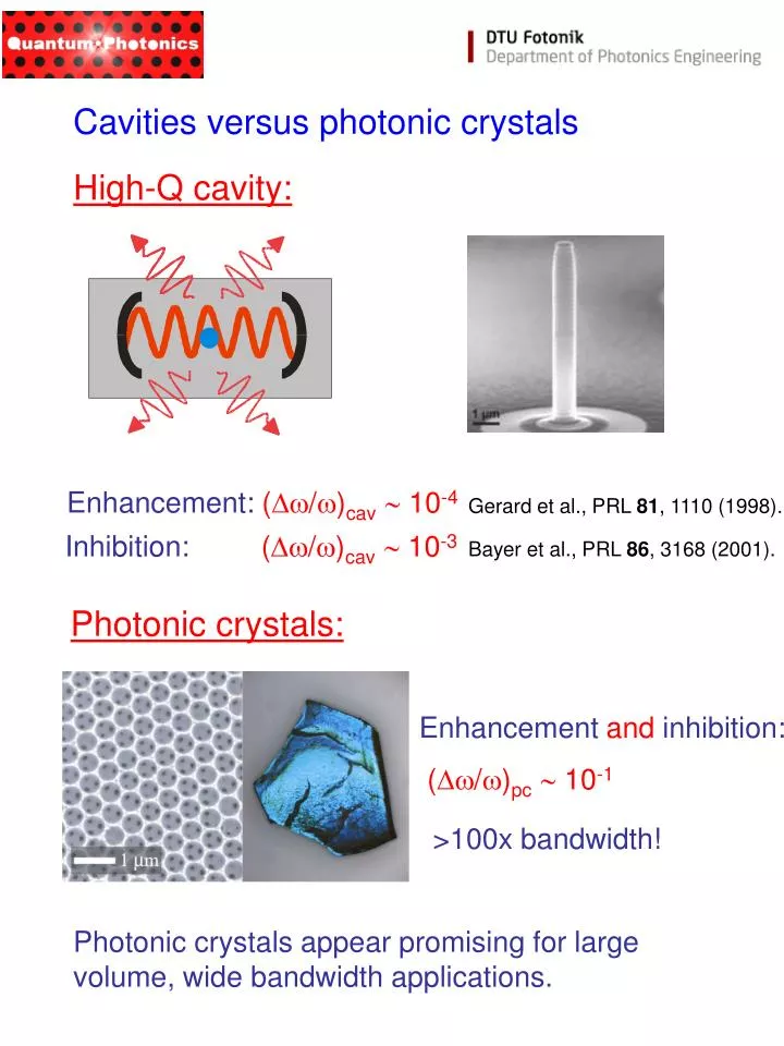
Photonic crystals:. Enhancement and inhibition:. ( /) pc 10 -1. >100x bandwidth!. Photonic crystals appear promising for large volume, wide bandwidth applications. Cavities versus photonic crystals. High-Q cavity:. Enhancement: ( /) cav 10 -4.

E N D
Photonic crystals: Enhancement and inhibition: (/)pc 10-1 >100x bandwidth! Photonic crystals appear promising for large volume, wide bandwidth applications. Cavities versus photonic crystals High-Q cavity: Enhancement: (/)cav 10-4 Gerard et al., PRL 81, 1110 (1998). Inhibition: (/)cav 10-3 Bayer et al., PRL 86, 3168 (2001).
Frequency Beyond Wigner-Weisskopf theory If LDOS varies strongly with frequency Wigner-Weisskopf theory breaks down. Emitter tuned close to a photonic band edge. spectrum of unpert. emitter Non-Markovian dynamics, i.e. memory effects, must be taken into account. Kristensen, Koenderink, Lodahl, Tromborg & Mørk, Opt. Lett. 33, 1557 (2008).
Excited state population Time Fractional decay of an emitter Using an idealized LDOS for an inverse opal with a photonic bandgap leads to the prediction of a fractional decay of the emitter The emitter decays only partly close to the band edge Fractional decay is also predicted to occur using the ‘real’ LDOS calculated for specific photonic crystals, see reference below. So far no experimental observations! Kristensen, Koenderink, Lodahl, Tromborg & Mørk, Opt. Lett. 33, 1557 (2008).
Sketch of the DOS for a photonic crystal cavity: Photonic crystal cavities Introducing defects in a photonic crystal breaks the symmetry locally and can induce allowed states in the band gap. Light is localized near the defect region.
Design of photonic crystal nanocavities Q ~ 45.000 V ~ 6 Voptimum Voptimum= (l/2n)3 Can obtain high Q-factors together with an extremely small mode volume V ~ (250 nm)3 nanocavity for light where light-matter interaction is strongly enhanced. Akahane et al., Nature 425, 944 (2003).
Electrically controlled vacuum Rabi splitting in photonic crystal nanocavity An important advantage of solid-state systems is that they can be tuned and pumped efficiently by voltages and currents. Laucht, Hofbauer, Hauke, Angele, Stobbe, Kaniber, Böhm, Lodahl, Amann, and Finley, New Journal of Physics 11, 023034 (2009).
Slow light in photonic crystal waveguides Group velocity vanishes ideally at Brioullin zone boundary local density of states diverges
Photonic crystal waveguides Vlasov et al., Nature 438, 65 (2005).
Experimental demonstration of slow light Group index: Vlasov et al., Nature 438, 65 (2005).
Coupling single quantum dots to a photonic crystal waveguide Waveguide mem- brane containing quantum dots. QDs coupled to the waveguide decay much faster than uncoupled QDs. Lund-Hansen, Stobbe, Julsgaard, Thyrrestrup, Sünner, Kamp, Forchel & Lodahl, Phys. Rev. Lett. 101, 113903 (2008).
Highly efficient photonic crystal waveguide single-photon source Emission efficiency into the waveguide: Lund-Hansen, Stobbe, Julsgaard, Thyrrestrup, Sunner, Kamp, Forchel & Lodahl, Phys. Rev. Lett. 101, 113903 (2008).