Download
1 / 18
180 likes | 722 Views
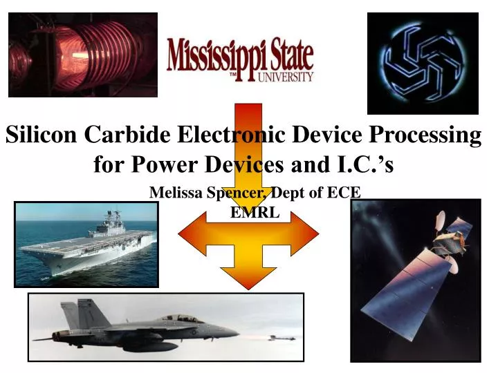
Silicon Carbide Electronic Device Processing for Power Devices and I.C.’s. Melissa Spencer, Dept of ECE EMRL. SiC devices are needed by DoD and Industry High-temperature, power and frequency electronics Critical future technology to replace silicon microchips

E N D
Silicon Carbide Electronic Device Processing for Power Devices and I.C.’s Melissa Spencer, Dept of ECE EMRL
SiC devices are needed by DoD and Industry High-temperature, power and frequency electronics Critical future technology to replace silicon microchips EMRL is a devicefabrication research laboratory focusing on SiC technology Reactive Ion Etching (RIE) is one of the key manufacturing steps in semiconductor technology SiC 3rd strongest material, only RIE can etch it to make devices Why SiC?
Reactive Ion Etching Plasma Chemistry Etch: SF6+He, H2, O2 Ash: O2 RF Power 10-100 W typical Pressure 100-600 mT RF energy strikes a plasma which etches the SiC material
Etched Devices* These SiC samples were etched using our RIE process *G. E. Carter, J. B. Casady, M. Okhuysen, J. D. Scofield, and S. E. Saddow, ICSCRM’99
Problem • Changes in plasma dielectric constant, P, plasma impedance, ZP, variation • This changes the RF power transfer to the plasma Pin = Preflected + Pplasma • The etch rate is a sensitive function of Pplasma • Manual impedance matching makes the etching process highly operator dependent • Therefore RIE process variations unavoidable
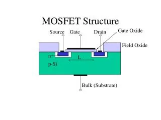
RIE Etch Rate SEMICONDUCTOR DEVICE CROSS-SECTION ETCH 2.5 mm • RIE etch rate recipes are critical in forming devices • Devices are fabricated by forming, patterning, and etching layers • Each layer must be precisely etched for the device to function properly IC Hair Each one of these layers are very thin so etching is critical! Each layer is patterned and etched
Power Dependence* 1600 1400 Power (W) vs Etch rate (A/min) 1200 1000 Etch rate (Angstroms/minute) 10 Percent power change 20% etch rate variation 800 600 400 SF6 :O2 (5:10 sccm) Pressure = 100 mT Electrode to sample spacing = 25.4 cm 200 0 0 40 5 10 30 35 15 20 25 Power (W) Etch rate is a sensitive function of plasma power *J. Bonds, G. E. Carter, J.B. Casady and J.D. Scofield, Spring MRS Meeting, April 2000
Automated RF Tuner • Detects load impedance, ZP, changes • Automatically matches ZP, making the RIE process more repeatable • Allows more precise RIE recipes to be performed • Devices with finer features may be fabricated
Impedance Matching The load impedance is matched to the source impedance by a “T” network: X1 X2 PForward X3 RF Source ZP =ZS PReflected X1, X2 variable capacitors and X3 variable inductance Control algorithm to minimize PR vs. ZP
Implementation • Hardware • Variable Impedance Devices • Detection Circuitry for PForward and PReflected • Micro-Controller • Servo Motors (impedance device tuning) • AC to DC Converter • A/D Converters • Software • Impedance Tuning Algorithm • Monitoring Software
Automated RF Tuner Detection Circuitry Inductor Servos Capacitors Stamp
Vary Impedance Matching Algorithm Detect Reflected Power Vary Impedance?
System Block Diagram MFJ-962D RF in Detection Circuitry for Forward and Reflected Power Monitoring PC Servo Motor/Driver Micro-Controller Servo Motor/Driver Servo Motor/Driver RF out Goal: Maintain constant power transfer
Future Work • Modular Device • Feedback circuitry can be replace with other detection devices • Communication with computer • Reflected Power could be compensated with RF source • Automate other power related parameters • Electrode spacing could be varied automatically to utilize optimal spacing
Research Impact • Component Production • Mississippi Small Business • SBIR’s Prototyping LAM 9400 Etcher AIXTRON SiC Reactor EMRL • SiC CVD Epi Research • Materials Characterization • Multi Wafer SiC Epi • Sub-micron lithography • Multi Wafer Plasma Etching • Multi Wafer PECVD • Multi Wafer Metal Deposition • Device Design & Fab • Systems Production • Northrop Grumman • GE/Lockheed Martin
Acknowledgements • This project has been a collaborative effort by members of • the Emerging Materials Research Laboratory at MSU and • would not have been possible without the assistance of the • EMRL researchers and staff. • Dr. Mazzola and Dr. Casady for their support of this project • Janna Bonds and Geoff Carter for their RIE assistance • Dr. Donohoe for his help on RF concepts and impedance • matching theory • Dr. Saddow my project advisor
Silicon Carbide Electronic Device Processing for Power Devices and I.C.’s Melissa Spencer, Dept of ECE EMRL