Download
1 / 52
530 likes | 686 Views
Group 27-SenseWalk . Mark Applegate (EE) Sara Belichki (CpE) Matthew Czarniak (CpE) Nicholas Heintze (EE). Motivation & Project Goals. Improve the independence and quality of life for the visually impaired. Optimize a tool commonly used by the visually impaired. How to we do this?.

E N D
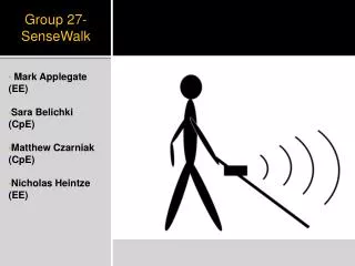
Group 27-SenseWalk Mark Applegate (EE) Sara Belichki (CpE) Matthew Czarniak (CpE) Nicholas Heintze (EE)
Motivation & Project Goals • Improve the independence and quality of lifefor the visually impaired. • Optimize a tool commonly used by the visually impaired.
How to we do this? • Sonar:detect upcoming obstacles and vibrate a motor attached at the user’s white cane. • GPS: the SenseWalk will hold the user’s saved routes to guide them when needed. • Audio: the user will be alerted of upcoming instructions as they go about a route.
Sense Walk System Design MCU GPS Sonar SD Card Digital Compass Audio Power Supply
Microcontroller MCU GPS Sonar SD Card Digital Compass Audio Power Supply
Microcontroller Requirements • The SenseWalk requires a microcontroller that contains • High flash memory-between 256 KB-512 KB • High frequency • SPI connection • Enough GPIO pins for the needed peripherals • Low power
Microcontroller Selection ATmega2560
Sonar Design MCU GPS Sonar SD Card Digital Compass Audio Power Supply
Sonar Specs and Requirements • Distance From 1 meter to 3 meters • Sonar operate at 40kHz • Not affected by noise • Microcontroller calculate distance • Vibrate a motor at different magnitudes proportional to distance
Ultrasonic Drive Circuit Options • 555 Timer • Square wave is highly distorted by load. • Phase shift Oscillator • Square wave is distorted by load. • 40kHz Crystal- CMOS Inverter Oscillator • Minimum distortion
Ultrasonic Transmitter Circuit Hex Inverter
Ultrasonic Receiver Circuit Quad Op Amp
Sonar Modifications • Sonar: Second MCU is needed to do the calculations • Sonar: High side switching needed to get rid of noise • Sonar: More gain is needed to pick up objects at a further distance
Sonar Selection • Parallax Ultrasonic Distance Sensor • Interfaces directly with MCU • Libraries available to calculate distance via MCU • Provides ADC conversion of sonar readings onboard the sensor • Works from 2 cm to 3 m range
Audio MCU Sonar Audio GPS Digital Compass SD Card Power Supply
Audio Requirements • Needs an audio decoder to decode MP3 files into digital audio data • Be able to relay audio data to a headphone jack • Be able to play certain tracks in realtime depending on current GPS status that is being relayed to the microcontroller
Audio Selection • VS1053B audio decoder to decode MP3 files via input bitstream through SPI • Stores MP3 files on a microSD card • MCU determines when to play a track from audio module • Audio sent out to headphone jack
Navigation Design MCU GPS Sonar SD Card Digital Compass Audio Power Supply
SD Card • San Disk 4 GB • Petite FatFS • Stores Waypoints & MP3 Tracks
Loading Waypoints on SD Card • Use route planner to create CSV / GPX • Upload CSV file with waypoints to SD
Routing • Distance Calculation: (Haversine) • Angle to Waypoint Calculation:
Routing Continued • Used current heading and angle to waypoint to determine how to orient user • Normalized the distance from the current heading to the new heading in the clockwise direction, counter clockwise direction, and also subtract the current heading from the final heading. • Pick the smallest of the three to be the correct difference.
Software Class Diagram SenseWalk SDCard Compass Bluetooth Sonar GPS Init() getDirection() getCurrentCoordinates() getCurrentWaypoint() sendBluetooth() calculateSonar() determineRelativePos() determineCorrection() Sonar SDCard Audio Compass GPS determineDistance() sendMotorCommand() PlayTrack() OpenFile() CloseFile() ParseWaypoints() CurrentWaypoint() calibrateCompass() currentDirection() establishConnection() currentCoordinates()
Power Supply MCU GPS Sonar SD Card Digital Compass Audio Power Supply
AC-DC Efficiency Requirements • Energy Star Requirements have become industry standard “AC-DC External Power Supply- An external AC-DC power supply is an EPS designed to convert line voltage ac input into lower voltage dc output.” [1] Output Power: 14.4W Minimum Efficiency Requirement: 73% [1] http://www.energystar.gov/ia/partners/prod_development/revisions/downloads/FinalSpecV2.pdf
Flyback Switching Converter • High Efficiency 80+ % capable. • Least costly of all isolated switching power supplies. • Full isolation capable. • Ideal for 0-200Watts. • Limited to 200Watts due to high peak switch currents. Magnetic & Capacitive Component Issues Controller & FET selection EMI design issues
Continuous Conduction Mode VS Discontinuous Conduction Mode CCM DCM DCM • Lower energy in transformer= smaller transformer • Less windings = lower I2R Losses • Higher ripple current = output capacitor ESR requirements • Higher transistor and diode peak current requirements CCM Lower ripple current Lower transistor and diode peak current requirements Right Half Plane Zero requires complicated control loop Higher energy in transformer = larger transformer
Transformer Design DCM • Primary Inductance: 1.078mH • Primary Peak Current: 0.75A • Max Input RMS Current: 0.32A • Max Output RMS Current: 2.08A • Turn Ratio: 8.94 • Primary & Secondary Wire Size • Core Material Selection • Gap Length, Total Winding Area
MOSFET Selection • Power MOSFET required - 600V and >2 Amps. • Experiment with MOSFETs to find best fit for efficiency. • Switching losses - Low parasitic capacitances and fast rise/fall times will combat switching losses. • Conduction losses - Low Rds(on) will combat conduction losses.
Li-ion Switching Battery Charger • Three states: Preconditioning, Constant Current, Constant Voltage [2] Courtesy of Texas Instruments
Li-ion Battery • Capacity: 2600 mAh • Working Voltage: 7.2V • Peak Voltage: 8.4V • Cut off voltage: 5.5 V • Max Charging Current: 2 Amp • Length: 2.8" • Width: 1.45" • Height: 0.8" • Weight: 3.5 Oz
Linear Vs Switching Regulators Linear • Low Cost • Low Design Complexity • Low Noise • Small size • Poor Efficiency <40% • High Heat Dissipation Switching • High Efficiency 80+% • Extended Battery Life • Higher Cost • Higher Design Complexity
Console Design • PCB resides in console • Console affixed to any standard white cane using a mounting unit • Switches on side of console allow user the freedom to turn on and off select features such as audio, GPS, or sonar.