Download
1 / 15
150 likes | 304 Views
Clock & Control Card Status 31 March 2009 Martin Postranecky / Matt Warren. CALICE CCC – First Prototype. CALICE CCC – First Prototype. CCC - Custom Hardware. SMAs (vertical). HDMIs. LEMO (NIM). CPLD. Debug Header. RS232. Add-ons interface. CCC - Overview Schematic. CLOCK.

E N D
Clock & Control Card Status31 March 2009Martin Postranecky / Matt Warren
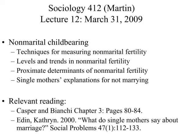
CALICE CCC – First Prototype Martin Postranecky / Matt Warren
CALICE CCC – First Prototype Martin Postranecky / Matt Warren
CCC - Custom Hardware SMAs (vertical) HDMIs LEMO (NIM) CPLD Debug Header RS232 Add-ons interface Martin Postranecky / Matt Warren
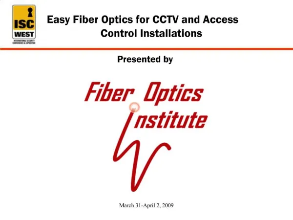
CCC - Overview Schematic CLOCK AUTO/ XTAL SW LVDS on SMA LVTTL on Lemo 8x LVDS on HDMI MPX +PLL NIM/TTL on Lemo 8x LVDS on SMA 2x LVTTL on Lemo ~50 MHz 2x NIM on Lemo X-TAL ASYNC clock LVDS on SMA SW 8x LVDS on HDMI ECL on 2pin Lemo DELAY Controls (SYNCCMD, BUSY-IN etc) 4x LVDS on SMA 4x NIM on Lemo 4x 4 SW-2 5->1 4 8x LVDS on HDMI GEN (was BUSY) LVDS on SMA CPLD (Xilinx Coolrunner XCR3128XL-7) SW-3 2->1 8x LVDS on HDMI NIM on Lemo 4 o/c TTL on Lemo SPARE (DATA_D2L) 8x LVDS on HDMI LVTTL on Lemo RS232 DEBUG 4x 8way DIL PCB Header Martin Postranecky / Matt Warren
CCC - Logic and Interfaces • CPLD ( XCR3128XL-7 ) • RS232 interface as a means of control • Many buffers, 0Ω resistors and solder links for better signal integrity, isolation and configuration Signal Inputs: • CLOCK • 1x LVDS ( SMA DC) • 1x LVTTL DC ( Lemo ) • 1x NIM / TTL ( Lemo ) AC/DC • ASYNC • LVDS ( SMA ) DC • ECL ( 2 pin LEMO ) AC • Controls ( SYNCCMD, BUSY etc. + more ) • 4x LVDS ( SMA ) • 4x NIM / TTL ( Lemo ) AC/DC • HDMI I/O: x8 • - LVDS AC/DC • OUT: • CLOCK • ASYNC • TRAINSYNC • IN: • GEN ( was BUSY ) • SPARE( DATA_D2L ) Signal Outputs: • CLOCK • 2x LVTTL on Lemo • 2x NIM on Lemo • 2x LVDS on SMA • 8x LVDS on DIL Header • TRAINSYNC • LVTTL on Lemo • GEN ( was Busy ) • LVDS on SMA • NIM on Lemo • O/C-TTL on Lemo • Spare ( DATA_D2L ) • LVTTL on Lemo Martin Postranecky / Matt Warren
Some Hardware Details • Clock: • PLL/MUX - ICS581-02 • +/-150 ps jitter • 45min/55max Duty Cycle • Failover if external clock missing for 3 cycles. • Local Osc. 100 MHz/2 = 50% duty-cycle 50MHz • CPLD: Xilinx CoolRunner XPLA3 XCR3128XL-7 • 3.3V, low power • 128 macrocells with 3,000 usable gates • 5.5ns pin-to-pin logic delays • Extra IO via IDC header. • Single 6U PCB with connectors at both edges • Separate PSU • Clock Delay Option to CPLD – 64 x 0.5ns • For signal de-skew ( CLOCK unaffected ) Martin Postranecky / Matt Warren
LVTTL Output Stand-alone Clock Martin Postranecky / Matt Warren
LVTTL – Output Clock Jitter Martin Postranecky / Matt Warren
CCC - Current Status • 10x boards manufactured and assembled in 2008 • 10x separate Power Supply units being assembled in 2009 • 10x CCC undergoing testing in 2009 : - 9x program OK - number of irritating problems ( dry joints, missing connections, etc. ) - 1x fails firmware programming ( suspect CPLD connections ) • Aim to have 9x tested and working units in April • Basic ‘simple’ self-testing firmware now on CPLD • ‘Run’ firmware is in development : COMING SOON ! • Serial Interface details on Twiki • Hardware Manual draft : http://www.hep.ucl.ac.uk/~mp/CALICE_C-C/CALICE_C-C_CCC-MANUAL-3.txt • TWIKI pages : https://twiki.cern.ch/twiki/bin/view/CALICE/ClockControlCard https://twiki.cern.ch/twiki/bin/view/CALICE/CCCSerialInterface Martin Postranecky / Matt Warren
Spare slides…. FEW PREVIOUSLY SHOWN / SPARE SLIDES Martin Postranecky / Matt Warren
DIF DIF DIF DIF Detector Unit Detector Unit Detector Unit Detector Unit Storage CALICE - DAQ architecture Detector Unit: ASICs DIF :Detector InterFace connects Generic DAQ and services LDA :Link / Data Aggregator – fan-out / in DIFs and drives link to ODR ODR :Off Detector Receiver – PC interface for system. CCC :Clock & Control Card: Fanout to ODRs ( or LDAs ) CONTROL PC: DOOCS GUI ( run control ) DAQ PC ODR LDA Control PC (DOOCS) CCC LDA DAQ PC ODR Martin Postranecky / Matt Warren
CCC - Timing Overview • C+C provides a fast clock ( CLOCK ) • Assumed to be ~50 MHz, local or machine • Stand-alone clock can be 50 or 100 MHz • CCC does NOT support varied delays on individual outputs • CCC card can adjust timing of synchro-signals wrt. CLOCK Martin Postranecky / Matt Warren
CCC - Link Interface • CCC can connects to LDA, DIF and ODR using the ‘standard’ HDMI cabling and connectors and pinout ( Clink ) • But only a subset of the signals/functions used • CCC can be used as a pseudo-LDA for stand-alone DIF testing • A distinction is made between fast and fixed latency signals. • Fast signaling is asynchronous and uses a dedicated line to transfer a pulse. No attempt is made to encode data • Fixed-latency signaling will not arrive fast, but will arrive a known latency after reception by CCC Martin Postranecky / Matt Warren
CCC - Link Signals CLOCK Machine clock (50 -100 MHz) TRAINSYNC_OUT Synchronisation of all the front-end slow clocks An external signal will be synchronized to the clock and transmitted as a single clock-period wide pulse to the LDA To allow communicating with a stand-alone DIF, the CCC board will can be configured to send the LDA 8b/10b serialised command for train-sync ASYNC_OUT Transfer asynchronous triggers as fast as possible GEN_IN General purpose signal for use in communicating with the CCC ( and therefore run control ) system. A hardware OR of these signals is available on the CCC Martin Postranecky / Matt Warren