Download
1 / 30
300 likes | 422 Views
Geometrical Optics and Basic Imaging Light Paths of the Bright Field Microscope. E. D. Salmon University of North Carolina at Chapel Hill. Major Imaging Functions of the Microscope.

E N D
Geometrical Optics and Basic Imaging Light Paths of the Bright Field Microscope E. D. Salmon University of North Carolina at Chapel Hill
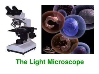
Major Imaging Functions of the Microscope • Magnification: Needed to overcome resolution limitations produced by finite size of recording sensors- rods and cones in eye, silver grains in film; pixels in CCDs • Resolution: Limited by lens aberrations and finite wavelength of light • Contrast: How to make resolvable structural detail visible-absorbing stains, phase contrast, DIC, Pol., immunofluorescence, fluorescent analogs, GFP-fusion proteins, other fluorescent molecular probes
Some Visible Spectrum Light Sources The eye is most sensitive to green light!
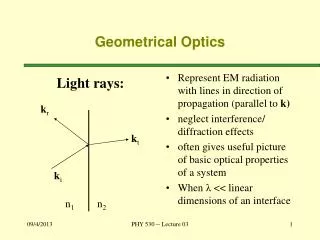
Primer on Geometrical Optics • Light moves in straight lines through homogeneous media at velocity: v = c/n(l) • Example values for n(546nm): Air 1.0 Water 1.3333 Cytoplasm 1.38 Glycerol 1.46 Crown Glass 1.52 Immersion Oil 1.515 Protein 1.51-1.53 Flint Glass 1.62
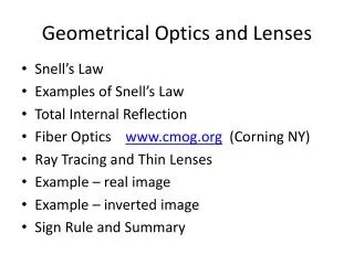
Reflection and Refraction at Transparent Surface Snell’s Law of Refraction n1sin(Qi) = n2sin(Qr)
Total Internal Reflection Can Occur Snell’s Law of Refraction n1sin(Qi) = n2sin(Qr)
Total Internal Reflection is Used to Re-Direct Light Prism Fiber Optic Light Guide
Homework 1. A beam of light in glass hits a surface at an angle. At what angle does the light just become total internally reflected if the glass has a refractive Index of 1.52 and the interface has a refractive index of : a. Air b. Water c. Immersion oil In each case, what is the numerical aperture (NA) of the beam relative to the normal to the interface?
Refraction at Curved Lens Surfaces: Action of Convex or Concave Lenses F’ is Primary Front Focal Point of Lens
Basic Action of Converging Lenses Light parallel to the optical axis comes into focus at a point F’, the back focal point, located one focal length, f, from principle plane (PPL) of the lens. Parallel light at angle, Q, to the optical axis comes into focus at a point, F”, located in the back focal plane and at a distance a = fsin(Q) from the focal point, F’.
Homework: What is an easy way to measure the approximate focal length of a lens
Basic Action of Converging Lenses (cont.) Light emanating from the front focal point, F’, located a distance, f, on the optical axis from the PPL will emerge Parallel to the optical axis. Light emanating from a point in the front focal plane, FFP, at distance a from the optical axis, will emerge as a parallel beam of light at angle, Q, to the optical axis, where a = fsin(Q). Example: Flashlight
Real-Image Formation As Object Moves Closer to Lens
Three Light Rays Can Define Real Image Formation M = I/O =i/o 1/i +1/o = 1/f
Resolution Limitations of the Human Eye Limits to Accommodation Unresolved Resolved Resolution Test
Ocular is a Single Lens Magnifier Magnification (angular) = 250 mm/f
Homework: What is The Ocular Focal Length for the Following Magnifications? • 5X _________ • 10X _________ • 20X _________ • 25X _________
The Objective Forms a Real Image At the Ocular Front Focal Plane: The Primary or Intermediate Image Plane (IIP) Conventional Optics Objective with finite Focal Length (Optical Tube Length, OTL, Typically 160 mm) Mob = OTL/fob Total Magnification = Mob x Moc = OTL/fob x 250mm/foc
Homework: For Finite Focal Length Objective and OTL = 160 mm, what is focal length for the following Objective Magnifications • 4X _________ • 10X ________ • 20X ________ • 40X ________ • 60X ________ • 100X _______
How to Insert Filters Above Objective Without Inducing Image Aberration Mob = ffocusing/fob
Zeiss introduced infinity corrected objective for biomedical scopes in late 1980’s, Nikon, Leica and Olympus followed by Mid-1990’sAlso, field of view in ocular enlarged from 18 mm to 24-25 mm.
Numerical Aperture (NA) of Collection (a) or Illumination (b) a. b.
Homework for Thursday: Go to http://micro.magnet.fsu.edu/primer/index.html and work through: • Light and color • Anatomy of Microscope: -Introduction -concept of Magnification -Microscope Optical components: -Geometrical construction of Ray Diagrams -Perfect Lens Characteristics -Perfect 2 Lens Characteristics