Download
1 / 30
390 likes | 585 Views
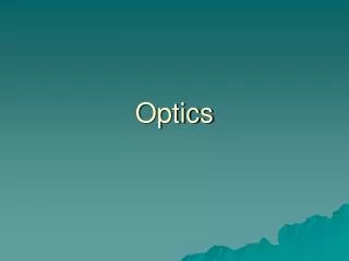
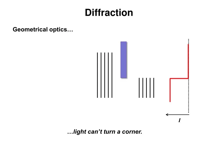
Diffraction. Geometrical optics…. I. … light can’t turn a corner. Diffraction. Physical optics…. Francesco Maria Grimaldi (1618 - 1663). I. … actually, it can. Huygens-Fresnel principle. every point on a wavefront may be regarded as a secondary source of spherical wavelets.

E N D
Diffraction Geometrical optics… I …light can’t turn a corner.
Diffraction Physical optics… Francesco Maria Grimaldi (1618 - 1663) I …actually, it can.
Huygens-Fresnel principle every point on a wavefront may be regarded as a secondary source of spherical wavelets The propagated wave follows the periphery of the wavelets. Huygens, just add the wavelets considering interference!
Huygens-Fresnel principle If one perturbs a plane wavefront, the Huygens wavelets will no longer constructively interfere at all points in space. Adding the wavelets by physical optics explains why light can turn corners and create fringes around images of objects.
Obliquity factor (oblique obscure?) - wavelets propagate isotropically—in forward and reverse directions - to use the Huygens approach, modify amplitude of wavefront as a function of q:
Calculating the diffracted wave spherical waves: Fresnel-Kirchhoff diffraction integral: phase shift obliquity factor In general, not an easy task. Lucky for you, Fresnel made it simpler.
Diffraction dudes: Fresnel and Fraunhofer Contemporaries, but not collaborators (nor competitors).
Fraunhofer: both incident and diffracted waves may be considered to be planar (i.e. both S and P are far from the aperture) Fresnel: occurs when either S or P are close enough to the aperture that wavefront curvature is not negligible Fresnel vs. Fraunhofer diffraction S P
Irradiance x1 Fresnel diffraction from a slit irradiance vs. position, just after a slit illuminated by a laser
From Fresnel to Fraunhofer diffraction Incident plane wave
Fresnel vs. Fraunhofer diffraction view from source: view from point of interest: near field where d represents p or q (=distance from source or point to aperture) A is aperture area
Fresnel number, F source: Fresnel diffraction occurs when: point: Fraunhofer diffraction occurs when: where h = aperture or slit size l = wavelength d = distance from the aperture (p or q)
Diffraction patterns Screen with array of slits ZT = 2d2/l Fresnel diffraction from an array of slits: the Talbot effect • one of the few Fresnel diffraction problems that can be solved analytically • beam pattern alternates between two different fringe patterns http://www.flickr.com/photos/gaeloso/4256791024/
Rolling out the optical carpet: Talbot effect http://physicsworld.com/cws/article/print/133
Getting into the zone Fresnel’s approach to diffraction from circular aperatures zone spacing = l/2: r1 = r0 + l/2 r2 = r0 + l r3 = r0 + 3l/2 rn = r0 + nl/2 … these are called the Fresnel zones
Stay in the zone as we draw a phasor diagram where each zone is subdivided into 15 subzones 1 2 3 4 5 5½ half-period zones • obliquity factor shortens successive phasors • circles do not close, but spiral inwards • amplitude a1 = A1 : resultant of subzones in 1st half-period zone • composite amplitude at P from n half-period zones:
Adding up the zones individual phasors composite phasors for large N, resultant amplitude= half that of zone 1
Implications of Fresnel zones For N contributing Fresnel zones, If N is small, a1 ~ aN for odd N, AN ~ a1 for even N, AN ~ 0 If N is large (i.e. huge aperture) aN 0 for any N, AN ~ ½ a1
. Part 1 Implications of Fresnel zones strange A circular aperture is matched in size with the first Fresnel zone: AP = a1 Now open the aperture wider to also admit zone 2: AP~ 0 ! Now remove aperture, allowing all zones to contribute: AP = ½ a1 !!! (Irradiance only ¼ !) What is amplitude of the wavefront at P?
. Part 2 Implications of Fresnel zones strange • A circular disk is matched in size with the first Fresnel zone: • all zones except the first contribute • first contributing zone is the second • AP = ½ a2 • irradiance at center of shadow nearly the same as without the disk present! What is amplitude of the wavefront at P? How absurd! Siméon Denis Poisson (1781-1840)
The Fresnel zone plate 16 zones If the 2nd, 4th, 6th, etc. zones are blocked, then: Amplitude at P is 16 times the amplitude of a1 /2 Irradiance at P is (16)2 times!
An alternative to blocking zones Fresnel vs. plano-convex lens lens phases of adjacent Fresnel zones changed by p
Fresnel lighthouse lens • other applications: overhead projectors • automobile headlights • solar collectors • traffic lights
Fresnel’s treatment of straight edges cylindrical wavefronts diffracted by rectangular aperture: consider source to be a slit zones are now rectangular strips edge view:
Fresnel’s treatment of straight edges • again, zone spacing = ½ l • adding the phasors gives the endpoints of a Cornu spiral
Applications of the Cornu spiral straight edge: wire: