Download
1 / 27
380 likes | 590 Views
Geometrical Optics. Geometrical Optics. Optics is usually considered as the study of the behavior of visible light (although all electromagnetic radiation has the same behavior, and follows the same rules). The propagation of light can be described in two alternative views:

E N D
Geometrical Optics • Optics is usually considered as the study of the behavior of visible light (although all electromagnetic radiation has the same behavior, and follows the same rules). • The propagation of light can be described in two alternative views: a) As electromagnetic waves b) As rays of light • When the objects with which light interacts are larger than its wavelength, the light travels in straight lines called rays, and its wave nature can be ignored. • This is the realm of geometrical optics.
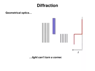
This can be described using geometrical optics This requires the use of full wave optics (Maxwell’s equations) Geometrical Optics Light can be described using geometrical optics, as long as the objects with which it interacts, are much larger than the wavelength of the light.
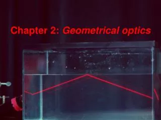
Propagation of Light Light propagates in straight lines (rays). This is valid as long as the light does not change the medium through which it propagates (air, water, glass, plastic), or finds an obstacle (interface). The velocity of light in air is c c = 3x10⁸ m/s The velocity of light in other media may be different from c (less than c).
Reflection and Transmission Most materials reflect light (partially or totally). For example, metals reflect light (almost totally) because an incident oscillating light beam causes the metal’s nearly free electrons to oscillate, setting up another (reflected) electromagnetic wave. Opaque materials absorb light (by, say, moving electrons into higher atomic orbitals). Transparent materials transmit light. These are usually insulators whose electrons are bound to atoms, and which would require more energy to move to higher orbitals than in materials which are opaque.
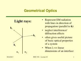
q1 = angle of incidence q1 Normal to surface Incident ray Surface Geometrical Optics Angles are measured with respect to the normal to the surface
q1 q’1 q1 = q’1 Reflection The Law of Reflection Light reflected from a surface stays in the plane formed by the incident ray and the surface normal and the angle of reflection equals the angle of incidence (measured to the normal)
q1 q’1 q1 = q’1 Reflection Specular and Diffuse Reflection Smooth specular shiny Rough diffuse dull
Two mirrors are placed at right angles as shown. An incident ray of light makes an angle of 30° with the x axis. Find the angle the outgoing ray makes with the x axis.
Medium 1 q’1 q1 Medium 2 q2 Refraction More generally, when light passes from one transparent medium to another, part is reflected and part is transmitted. The reflected ray obeys q1 = q’1.
Medium 1 q’1 q1 Medium 2 q2 Refraction More generally, when light passes from one transparent medium to another, part is reflected and part is transmitted. The reflected ray obeys q1 = q’1. The transmitted ray obeys Snell’s Law of Refraction: It stays in the plane, and the angles are related by n1sinq1 = n2sinq2 Here n is the “index of refraction” of a medium.
Medium 1 q’1 q1 Reflected ray Medium 2 Incident ray Refracted ray q2 Refraction q1= angle of incidence ’1=angle of reflection q2 = angle of refraction Law of Reflection q1= ’1 Law of Refraction n1 sin1= n2 sin2 nindex of refraction ni = c / vi vi = velocity of light in medium i
Index of Refraction The speed of light depends on the medium trough which it travels. The speed of light in a given medium is determined by the medium’s index of refraction n. Air, n = 1.000293 Glass, 1.45 n 1.66 Water, n = 1.33
Refraction l1=v1T The period T doesn’t change, but the speed of light can be different. in different materials. Then the wavelengths l1 and l2 are unequal. This also gives rise to refraction. q1 1 q1 2 q2 l2=v2T The little shaded triangles have the same hypoteneuse: so l1/sinq1= l2/sinq2, or v1/sinq1=v2/sinq2 q2 Define the index of refraction: n=c/v. Then Snell’s law is: n1sinq1 = n2sinq2
Example: air-water interface If you shine a light at an incident angle of 40o onto the surface of a pool 2m deep, where does the beam hit the bottom? Air: n=1.00 Water: n=1.33 (1.00)sin40 = (1.33)sinq sinq=sin40/1.33 so q=28.9o Then d/2=tan28.9o which gives d=1.1 m. 40 air water 2m q d
Example: air-water interface If you shine a light at an incident angle of 40o onto the surface of a pool 2m deep, where does the beam hit the bottom? Air: n=1.00 Water: n=1.33 (1.00)sin40 = (1.33)sinq sinq=sin40/1.33 so q=28.9o Then d/2=tan28.9o which gives d=1.1 m. 40 air water 2m q d
Example: air-water interface If you shine a light at an incident angle of 40o onto the surface of a pool 2m deep, where does the beam hit the bottom? Air: n=1.00 Water: n=1.33 (1.00) sin(40) = (1.33) sinq Sinq = sin(40)/1.33 so q = 28.9o Then d/2 = tan(28.9o) which gives d=1.1 m. 40 air water 2m q d Turn this around: if you shine a light from the bottom at this position it will look like it’s coming from further right.
Some common refraction effects
1 air water q2 Air-water interface Air: n1 = 1.00 Water: n2 = 1.33 n1 sin1 = n2 sin2 n1/n2 = sin2 / sin1 When the light travels from air to water (n1 < n2) the ray is bent towards the normal. When the light travels from water to air (n2 > n1) the ray is bent away from the normal. This is valid for any pair of materials with n1 < n2
Total Internal Reflection n1 > n2 q2 n2 q2 q1 qc q1 q1 n1 n2sin p/2 = n1sinq1 ... sinq1 = sinqc = n2 /n1 Total internal reflection: no light is refracted Some light is refracted and some is reflected
Total Internal Reflection • The critical angle is when q2 = p / 2, which gives qc = sin-1(n2/n1). • At angles bigger than this “critical angle”, the beam is totally reflected.
Find the critical angle for light traveling from glass (n = 1.5) to: • Air (n = 1.00) • Water (n = 1.33)
Example: Fiber Optics An optical fiber consists of a core with index n1surrounded by a cladding with index n2, with n1 > n2. Light can be confined by total internal reflection, even if the fiber is bent and twisted.
Example: Fiber Optics Find the minimum angle of incidence for guiding in the fiber, for n1 = 1.7 and n2 = 1.6
Example: Fiber Optics Find the minimum angle of incidence for guiding in the fiber, for n1 = 1.7 and n2 = 1.6 • sin qC = n2 / n1 • qC = sin-1(n2 / n1) • sin-1(1.6/1.7) 70o. • (Need to graze at < 20o)
TI I RI Reflection and Transmission at Normal Incidence Geometrical optics can’t tell how much is reflected and how much transmitted at an interface. This can be derived from Maxwell’s equations. These are described in terms of the reflection and transmission coefficients R and T, which are, respectively, the fraction of incident intensity reflected and transmitted. For the case of normal incidence, one finds: Notice that when n1=n2 (so that there is not really any interface), R = 0 and T = 1.