Download
1 / 79
880 likes | 1.16k Views
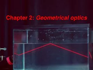
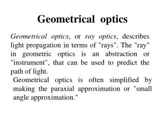
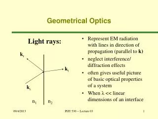
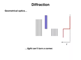
Geometrical Optics. Huygens Principle . Light can be treated as a series of RAYS with POINT SOURCES Thus, light can be treated as a plane wave (just as sound was, when it was far enough from the source). The Reflection of Light.

E N D
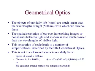
Huygens Principle • Light can be treated as a series of RAYS with POINT SOURCES • Thus, light can be treated as a plane wave (just as sound was, when it was far enough from the source).
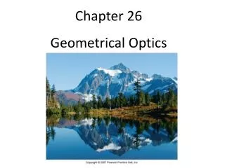
The Reflection of Light If a stone is dropped into a pond, circular waves emanate from the point where it landed. Rays, perpendicular to the wave fronts, give the direction in which the waves propagate.
The Reflection of Light As one moves farther from a point wave source, the wave fronts become more nearly flat.
The Reflection of Light The law of reflection states that the angle of incidence equals the angle of reflection:
The Reflection of Light Reflection from a smooth surface is called specular reflection; if the surface is rough, it is diffuse reflection.
Is it SPECULAR or DIFFUSE? • Reflection from a lake on a windy day • Reflection from the subway window • Reflection from Mr. State Police Officer’s sunglasses, as he pulls you over…
What is an Image? • An object is in front of a mirror. The light reflects off the mirror. What happens to the light? • The idea is that sometimes the light will reflect and then come back together again! • This is an IMAGE – a REFORMED representation of an object caused by reflected light rays that appear to come back together.
Real vs Virtual • If light rays actually do come back together, the image is REAL. • Real images are always INVERTED or turned UPSIDE DOWN or Inverted
Real vs Virtual • If it just LOOKS like there’s an image and the light never reconvened AT ALL, the image is VIRTUAL. • Virtual images are always Right Side Up or ERECT!
Magnification • This is always given by how far the IMAGE is from the mirror divided by how far the OBJECT is from the mirror. • Magnification is a UNITLESS quantity. • If M is negative, the image is inverted. If M is positive, the image is erect.
Forming Images with a Plane Mirror Light reflected from the flower and vase hits the mirror. Obeying the law of reflection, it enters the eye. The eye interprets the ray as having had a straight-line path, and sees the image behind the mirror.
p is the distance from object to mirror – called OBJECT DISTANCE • q is the distance from image to mirror – called IMAGE DISTANCE. • Mirror is origin. Real space is positive distance, behind mirror is negative.
h is the distance from object to mirror – called OBJECT HEIGHT • h’ is the distance from image to mirror – called IMAGE HEIGHT.
Ray diagrams show us how to build virtual images for study. • Light is approximated with straight lines (rays) • Note that the ACTUAL rays are solid lines, and rays created in “mirror space”, virtual rays, are represented with DOTTED lines.
Ray 1 comes in perpendicular to the mirror, on the normal • The angle of incidence (q) for the eye view above Ray 1 the pencil tip is 0° • This means the angle of reflection (q’) is also 0°.
Now, change the angle (see, I moved the eye). • Ray 2 has a new angle of incidence (q). It also has a reflected ray with the new angle of reflection (q’) • Trace 1 and 2 back to the reflected side to see where a virtual pencil point would be found. (the point where they meet) with virtual rays.
The REAL reflected rays diverge. We are forced to go to virtual rays for an image. • Tracing all possible point sources to the virtual source will give you the position of the virtual image.
Note that the object distance (p) is the same in magnitude (opposite in sign) as the image distance (q) for a flat mirror. • Likewise, height (h) will be the same as virtual height (h’)
Forming Virtual Images with a Plane Mirror Properties of Mirror Images Produced by Plane Mirrors: • A mirror image is upright, but appears reversed right to left. • A mirror image appears to be the same distance behind the mirror that the object is in front of the mirror. • A mirror image is the same size as the object.
Mirror Image • The plane mirror doesn't reverse up/down, all agree. It doesn't reverse left/right either. If you point a finger up, the image finger points up. If you point a finger to your right, the image points its finger to your right. When you keep all right/left references consistently in a fixed reference frame there's no problem. But there's more that's worth investigating here.
Mirror Image There are two basic things you have to think about • Semantics: “left vs right”. My left is not the same as your left. Right? • Shifting system of reference. Your reflection bounces back. If you flip your hand and look at it, you have a different frame of reference. Like the color addition/subtraction thing, some science makes little sense, semantically.
Spherical Mirrors A spherical mirror has the shape of a section of a sphere. If the outside is mirrored, it is convex; if the inside is mirrored, it is concave.
Spherical Mirrors Spherical mirrors have a central axis (a radius of the sphere) and a center of curvature (the center of the sphere). The distance between the mirror and C is often called the Radius of Curvature (R)
Spherical Mirrors This is a ray diagram for finding the focal point of a concave mirror. Remember, angle of incidence equals angle of reflection.
Spherical Mirrors When a mirror is convex, the focal point is behind the mirror. This leads, often, to a virtual image.
Spherical Mirrors For a convex mirror, the focal length is negative, as the rays do not go through the focal point. The opposite is true for a concave mirror.
We can PREDICT the image location! • Given p – the distance of the object to the mirror • Given R – the radius of curvature of the mirror and the focus f as 1/2R
What Rays To Draw??? • Now that we have more complex systems, we draw THREE RAYS to find our images. • The first is “In through parallel, Out through focus.” (P ray) • The second is “In through Focus, Out through Parallel” (F ray) • The third is “Straight through Normal” (will go through C in mirrors to get normal) (C ray) • These rules will apply for LENSES as well. SO LEARN THEM.
Ray Tracing and the Mirror Equation These three rays are illustrated here.
Ray Tracing and the Mirror Equation This image shows how these three rays are used to find the image formed by a convex mirror. The image is located where the projections of the three rays cross. The size of the image can also be determined.
The situations – moving left to righton the smartboard!! • CONCAVE mirror: • Object Left of C • Object ON C • Object between C and f • Object on f • Object between f and mirror • CONVEX mirror: • CLOSE to mirror • FAR from mirror
Concave mirror with object ON focal point. The image has Buzz-Lightyeared on us. Moving the object further in will produce VIRTUAL images.
Spherical Mirrors We have made the assumption here that the rays do not hit the mirror very far from the principal axis – so called Paraxial Rays. If the rays are not paraxial, the image is blurred. This is called spherical aberration, and can be remedied by using a parabolic mirror instead.
Spherical Mirrors When the Hubble Space Telescope was first launched, its optics were marred by spherical aberration. This was fixed with corrective optics.
Ray Tracing and the Mirror Equation Here are the sign conventions for concave and convex mirrors:
The Refraction of Light Light moves at different speeds through different media. When it travels from one medium into another, the change in speed causes the ray to bend. OMG that’s ugly
The Refraction of Light The speed of light in a medium is given by the index of refraction of that medium:
The Refraction of Light Here are some typical indices of refraction: Note, they’re all bigger than 1. Light is fastest where?
The Refraction of Light We can use the index of refraction to predict the angle at which light will refract:
A light ray traveling through air strikes a diamond at an angle of 60.0° to the the normal. Find the angle of refraction. G: θi = 60.0 ni= 1.00 nr = 2.42 U: θr F: nisin θi = nr sin θr S: 1.00(sin60) = 2.42 sinθr .866 = 2.42sinθr sinθr =.357 θr = sin-1(.357) = 21.0°
The Refraction of Light Basic properties of refraction:
The Refraction of Light Refraction can make objects immersed in water appear broken, and can create mirages.
The Refraction of Light If light enters a medium of lower index of refraction, it will be bent away from the normal. If the angle of incidence is large enough, the angle of refraction is 90°; at larger incident angles the light will be totally reflected.
The Refraction of Light This is called total internal reflection. The incident angle at which the angle of refraction is 90° is called the critical angle, C. Total internal reflection is used in some binoculars and in optical fibers.