Download
1 / 27
270 likes | 505 Views
Sequential Design. Part II. Output. A(t+1) =D A = AX + BX. B(t+1) =D B = AX. Y = AX + BX. 2-D State Table. Even Easier, State Diagrams:. Using State Diagrams. What about designing a state machine using J-K Flip Flops. Given this state table. Using J-K Flip Flops.

E N D
Sequential Design Part II
A(t+1) =DA = AX + BX B(t+1) =DB = AX Y = AX + BX
What about designing a state machine using J-K Flip Flops... Given this state table Using J-K Flip Flops JA = B KA = BX JB = X KB = AX + AX
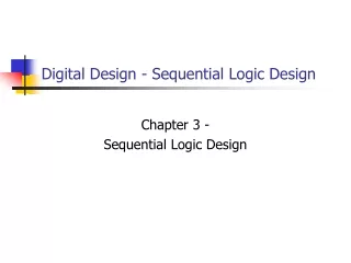
Sequential Circuit Design • Obtain either the state diagram of the state table from the statement of the problem • If only a state diagram is available from set 1, obtain the state table • Assign binary codes to the states • Derive the flip-flop input equations from the next-state entries in the encoded state table • Derive the output equations from the output entries in the state table • Simplify the flip-flop input equations and output equations • Draw the logic diagram with D flip-flops and combinational gates, as specified by the flip-flop input equations and output equations
Output based on state and present input Mealy Machine init C1 C2 s(t+1) State Register next state s(t) z(t) present state x(t) present input clk
Output base on state only Moore Machine init C2 C1 z(t) s(t+1) State Register next state s(t) present state x(t) present input clk
Example: A Sequence Recognizer Let’s detect the sequence “1101” in a bit sequence We need to “remember” what bits have passed by. If the input is a ‘1’ then move to state B and the output is a 0 (have not yet detected the “1101” sequence
Means first bit was a ‘1’ If we are at state B (which means that we have read a ‘1’ immediately beforehand) and the next input is a ‘1’ then we are making our way towards a successful “1101” read so move to state C.
The next bit we would like to read along our “1101” sequence is a ‘0’. So if we read a 0, go to State D -- notice output is still 0, we have not yet read the entire sequence. After state D we have succeeded if a ‘1’ is read so we will proceed and the output will now be ‘high’ or ‘1’
We set the output ‘high’ and go to State B. We don’t want to proceed to an E state, instead, if we have detected “1101”, we have not only detected the bit sequence but we also are on our way to detecting another “1101” sequence. Consider “1101101”. Two Sequences
Second bit is ‘0’ Begins with ‘0’ Third bit is a ‘1’ which means we have read a “111” seq. This puts us waiting for a ‘0’ A ‘0’ is the last bit (“1100”) back to the beginning. We must also fill in the “unsuccessful” states, ones in which we have not read a “1101” sequence.
Designing with D Flip-Flops Given the following: A(t + 1) = DA(A,B,X) = m(2,4,5,6) B(t + 1) = DB(A,B,X) = m(1,3,5,6) Y(A,B,X) = m(1,5)
Using k-maps to reduce the equations: A(t + 1) = DA(A,B,X) = m(2,4,5,6) B(t + 1) = DB(A,B,X) = m(1,3,5,6) Y(A,B,X) = m(1,5) BX BX A A DA = AB + BX DB = AX + BX + ABX BX A Y = BX
Significantly Reduces Logic Equations JA = BX JB = X KA = BX KB = AX + AX