Download
1 / 33
330 likes | 467 Views
GRAMM International Future Energy Challenge ‘07. Versamachine. Geoff Sanders, Richard Tan, Ankit Tripathi, Maung Myat, and Marc Hesse. Overview. Purpose Specifications System Description System Layout/Breakdown Labor Distribution Future Schedule to meet

E N D
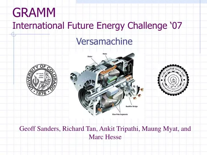
GRAMMInternational Future Energy Challenge ‘07 Versamachine Geoff Sanders, Richard Tan, Ankit Tripathi, Maung Myat, and Marc Hesse
Overview • Purpose • Specifications • System Description • System Layout/Breakdown • Labor Distribution • Future Schedule to meet • Marketability/Impacts and Sustainability • Challenges • Risks and Contingencies • Questions/Suggestions and Comments
Purpose Electric machine (motor): Works both as a starter (motoring) and an alternator (generator) Target: Electric Car, Hybrid Electric Car Reasons: • IFEC ’07 challenge • Save Space • Decrease Cost • Increase Efficiency
Specifications • Must provide 30 Nm of Torque startup. • Must motor up to 3000 rpm in 3-5 seconds • Must generate 1 KW of power • Must be at least 75% efficient • Must use NEMA frame 56, which is less than 7 inches in diameter http://www.leeson.com/
System Description • A two pole induction machine (motor) • Inverter/Rectifier • Motor Drivers • Gate Drivers (MOSFET DRIVER) • Micro-controller (TI / Freescale) • User Interface (using a CAN, RS 232 cable, PC Master) • RF/Bluetooth • Sensors (flux, torque, Hall, temperature, etc) • Power Supply
System Layout http://www.freescale.com/webapp/sps/site/overview.jsp?nodeId=02nQXGrrlPglzQMszY
Induction Machine (Motor) Squirrel cage induction machine with Variable Frequency (V/f) Control Will work on the principles of • Flux weakening/strengthening • Pole changing • Frequency Change
Torque-Speed curve change from starting point (30Nm) to 750 rpm
Torque-Speed curve change from 8 pole (750 rpm) to 4 pole (1500 rpm)
Torque-Speed curve change from 4 pole – 1500 rpm to 2250 rpm
Torque-Speed curve change from 4 pole – 2250 rpm to 3000 rpm
Generalized frequency and speed operation of motor Frequency-time Diagram Speed-time Diagram
Converter (Inverter/Rectifier) • Converter must fulfill two functions: • Inverter operation during starting and motoring up to 3000rpm • Rectifier operation during generating mode
Inverter • PWM Inverter • Operates during both motoring and generating modes • Converts DC supply voltage to 3 phase AC • Provides excitation current to stator windings • Additional specifications of the Inverter • Input dc voltage: VDC = 200V • Frequency range: 10-200 Hz • Current at low frequency of 15 Hz: Iline = 30 Apeak • Output voltage as high as possible for given input voltage
Rectifier • Rectifier • Operates only during generating • Converts AC current to DC in order to charge battery • Additional specification of the rectifier Output voltage: VDC = 200V @ 10 ADC maximum or at least deliver 1 kW to the battery at 200V with efficiency of 75%
Gate/Motor Drivers • Provide fast change in current to drive the gates of all IGBT/MOSFET switches in the converter
Sensors, Switches & Power Supply • Sensors • Operational sensors • Hall effect • Temperature • Position encoders • Testing • Torque transducer • Flux meter • Universal Dynamometer • Switches • winding switches • Pole changing • N reduction • Power Supply • 200 V DC
DSP/Micro-Controller • 3 Primary functions • Control switching of PWM inverter IGBT/MOSFET switches • Control winding switching • For pole changing • To reduce windings by half during 4 pole operation • Interact with user interface to produce desired operation
User Interface • PC Master Software • Serial port connection • Later use RF/Bluetooth http://www.freescale.com/files/product/doc/AN1948.pdf
PC Master Support • Freescale • 56F80x • 56F82x • 56F85x • Possibly supported by: • MC68HC08 (MC68HC908MR32) • MC68HC512 • MPC500
PC Master Features • Control the motor • Start-up/shut-down • Speed control • Read/change variables • Scope slower variables • Record fast variables • Stimulate variables • Send application commands with parameters • Display help items (block diagrams, characteristics) • Remote control of application through the internet
PC Master Windows http://www.freescale.com/files/product/doc/AN1948.pdf
Other parts • Voltage regulators • Resistors, capacitors, and heat sinks • Voltage shifters • RAM/ROM • ADC/DAC • RS232 serial port • UART • Clocks
Task Distribution • Maung/Richard • Part research and ordering • Design inverter/rectifier • Implement sensor circuits • Circuit schematics and PCB design • Ankit/Geoff • Motor design finalization and ordering • User interface/system controller • Marc/Geoff • User’s Manual • Micro-controller coding • Technical manual compilation • All • Documentation • Test/debug • Wire-wrap prototyping
Marketability • Almost all motor-vehicle manufacturers in the world can use it as it would • Increases overall efficiency of vehicle • Decreases overall cost • Take up less space • Target Manufacturing cost of $100 • Possible Patent
Challenges, Risks, and Contingencies • Challenges • This has never been done effectively! • What makes us think we will succeed where many have failed? • Risks • We could quite possibly fail to meet the IFEC specifications with our first (capstone) design. • We may be unable to make the machine automatically shift speeds and windings
Challenges, Risks, and Contingencies • Contingencies • For expo we will have a motor controlled with our controller that will run, although it may not meet the requirements dictated by IFEC. • If this occurs a permanent magnet rotor will be designed and used in place of the squirrel cage rotor in order to increase torque and efficiency • This is beyond the scope of capstone • Will be able to run each characteristic for testing using user interface to set frequency and manually switch windings
Questions / Suggestions http://www.smartquestion.com/images/sq_image.jpg