Download
1 / 24
250 likes | 543 Views
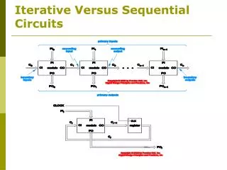
Iterative Versus Sequential Circuits. Iterative Versus Sequential Circuits. Iterative Versus Sequential Circuits. Synchronous Design Methodology. Synchronous systems – all flip-flops are clocked by the same common clock. To ensure reliable operation:

E N D
Synchronous Design Methodology • Synchronous systems – all flip-flops are clocked by the same common clock. • To ensure reliable operation: • Minimize and determine the amount of clock skew in the system. • Ensure that flip-flops have positive setup and hold time margins, including allowance for clock skew. • Identify asynchronous inputs and synchronize them with the clock. Ensure that the synchronizers have low probability of failure.
Clock Skew • Difference between arrival times of the clock at different devices.
Asynchronous Inputs • Synchronizer – circuit that samples an asynchronous input and produces an output that meets the setup and hold times required in a synchronous system.
Design Example • Shift and add multiplier • MPY/LPROD – Initially stores the multiplier, and accumulates the low-order bits of the product. • HPROD – Initially cleared, and stores the high-order bits of the product. • MCND – Stores the multiplicand. • If low-order bit of MPY/LPROD • Is 1 then F = 9-bit sum of HPROD and MCND. • Is 0 then F = HPROD extended to 9 bits.
Design Example • LDMCND_L=0 enables the multiplicand register U1 to be loaded. • LDHP_L=0 enables the HPROD register U6 to be loaded. • MPSY[1,0] • = 11 enables the MPY/LPROD register U2 to be loaded. • = 01 it shifts right during multiplication. • = 00 at other time to preserve register content. • SELSUM=1 multiplexers U7 and U8 select adders U4 and U5 output otherwise it selects HPROD. • CLEAR=1 the output of multiplexers U7 and U8 is cleared.
Design Example • LDMCND_L=0 enables the multiplicand register U1 to be loaded. • LDHP_L=0 enables the HPROD register U6 to be loaded. • MPSY[1,0] • = 11 enables the MPY/LPROD register U2 to be loaded. • = 01 it shifts right during multiplication. • = 00 at other time to preserve register content. • SELSUM=1 multiplexers U7 and U8 select adders U4 and U5 output otherwise it selects HPROD. • CLEAR=1 the output of multiplexers U7 and U8 is cleared.
Algorithmic State Machines - ASM • Partition the system into two parts: • Controller - ASM. • Controlled architecture – data processor.
ASM • Algorithm is a well defined procedure consisting of a finite number of steps to the solution of a problem. • Controller is a hardware algorithm or Algorithmic State Machine. • ASMs can serve as stand-alone sequential network model.
ASM • Conditional outputs – Mealy model. • State outputs – Moore model. • State time: • Transition period. • Stable period.
ASM • State box. • Represents one state in the ASM. • May have an optional state output list. • Single entry. • Single exit to state or decision boxes.
ASM • Decision box. • Provides for next alternatives and conditional outputs. • Conditional output based on logic value of Boolean expression involving external input variables and status information. • Single entry. • Dual exit, denoting if Boolean expression is true or false. • Exits to decision, state or conditional boxes.
ASM • Conditional output box. • Provides a listing of output variables that are to have a value logic-1, i.e., those output variables being asserted. • Single entry from decision box. • Single exit to decision or state box.
ASM Blocks • Consists of the interconnection of a single state box along with one or more decision and/or conditional boxes. • It has one entry path which leads directly to its state box, and one or more exit pathes. • Each exit path must lead directly to a state, including the state box in itself. • A path through an ASM block from its state box to an exit path is called a link path.
ASM Blocks • An ASM block describes the operation of the system during the state time in which it is in the state associated with the block. • The outputs listed in the state box are asserted. • The conditions indicated in the decision boxes are evaluated simultaneously to determine which link path is to be followed. • If a conditional box is found in the selected path then the outputs found in its output list are asserted. • Boolean expression may be written for each link path. The selected link paths are those that evaluate to logic-1.