Download
1 / 12
150 likes | 477 Views
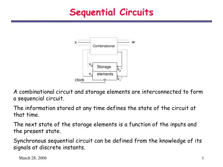
Sequential Circuits. Storage elements. A combinational circuit and storage elements are interconnected to form a sequencial circuit. The information stored at any time defines the state of the circuit at that time.

E N D
Sequential Circuits Storage elements A combinational circuit and storage elements are interconnected to form a sequencial circuit. The information stored at any time defines the state of the circuit at that time. The next state of the storage elements is a function of the inputs and the present state. Synchronous sequential circuit can be defined from the knowledge of its signals at discrete instants.
Sequential Circuit Design 1- Obtain either the state diagram or state table from the problem specs. 2- If we don’t have one already, obtain the state table from the state diagram. 3- Assign binary codes to the states. 4- Derive the FF input equations from the next state entries of the state table. 5- Derive the output equations from the output entries of the state table.
Sequential Circuit Design Design a sequence detector for the string “1101”. The output must be ‘1’ when the input matches this string x Sequence detector w clock
Sequential Circuit Design Mealy state machine (remember that in this state machine the output is dependent on input changes and states) 1/0 1/0 0/0 1/0 0/0 A B C D 0/0 1/1 0/0 Assign binary values to each state. Example: A = 00, B = 01, C = 11, D = 10
Sequential Circuit Design Make Table FROM present state & input TO next state & output, and FF inputs. A B C D
Sequential Circuit Design K-maps of the states & the outputs Q1 Q0 Output = IQ1Q0’ I Q1 Q0 J1 = IQ0 Q1 Q0 K1 = Q0’ I I Q1 Q0 J0 = I Q1 Q0 K0 = I’ I I
Sequential Circuit Design Layout Diagram J1 = IQ0 K1 = Q0’ J0 = I K0 = I’ Output = IQ1Q0’
Sequential Circuit Design – Moore State Machine Associate output with states only. This means that the output is also synchronous with the clock x Sequence detector w clock
Sequential Circuit Design Moore State Machine for the sequence detector 110 1 1 0 1 0 A/0 B/0 C/0 D/1 0 1 0 state A B C D A
Sequential Circuit Design VHDL implementation for the Moore sequence detector 110 ARCHITECTURE seq_det_arch of seq_det is BEGIN process1: PROCESS(CLK) VARIABLE STATE : STD_LOGIC_VECTOR(1 DOWNTO 0):= "00"; BEGIN IF (CLK = ‘1’) THEN CASE STATE IS WHEN "00"=> -- State A IF (X = '0') THEN STATE :="00"; W <= '0'; ELSE STATE := "01"; W <= '0'; END IF; WHEN "01"=> -- State B IF (X = '1') THEN STATE :="10"; W <= '0'; ELSE STATE :="00"; W <= '0'; END IF; ENTITY seq_det IS PORT ( CLK : IN STD_LOGIC; X : IN STD_LOGIC; W : OUT STD_LOGIC ); END seq_det; Continued…
Sequential Circuit Design VHDL implementation for the Moore sequence detector 110 WHEN "10" => -- State C IF (X = '1') THEN STATE := "10"; W <= '0'; ELSE STATE := "11"; W <= '1'; END IF; WHEN OTHERS => -- State D IF (X = '1') THEN STATE := "01"; W <= '0'; ELSE STATE := "00"; W <= '0'; END IF; END CASE; END IF; END PROCESS; END seq_det_arch;
Sequential Circuit Design VHDL implementation for the Moore sequence detector 110 Simulation waveform