Download
1 / 28
280 likes | 408 Views
Baseband Transceiver Design for the DVB-Terrestrial Standard. Advisor : Tzi-Dar Chiueh Student : Yi-Ju Chen Date : September 29 th , 2003. Outline. Review of DVB-T System Transmitter Block Diagram Channel Model Static Channel Dynamic Channel Receiver Architecture

E N D
Baseband Transceiver Design for the DVB-Terrestrial Standard Advisor : Tzi-Dar Chiueh Student : Yi-Ju Chen Date : September 29th , 2003
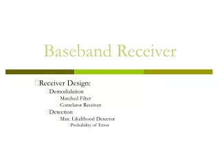
Outline • Review of DVB-T System • Transmitter Block Diagram • Channel Model • Static Channel • Dynamic Channel • Receiver Architecture • Coarse Boundary Detection • Integer CFO Estimation • WLS Fine CFO Estimation • Future Work • Reference
What is DVB-T ? • DVB-T stands for Digital Video Broadcasting – Terrestrial • Wireless video • DVB-T uses COFDM technique • DVB-T Transmit Block Diagram
System Parameters • Center frequency: 480MHz +i*6MHz • Region: 480MHz ~ 806MHz Channel 14 ~ Channel 69
Channel Model Static Channel Dynamic Channel
Fixed Reception where a directional receiving antenna mounted at roof level is used A receiving antenna height of 10m above ground level is considered to be representative Portable Reception Portable receiver with attached or built-in antenna Absence of receiving antenna gain and directivity Generally lower reception height Channel Model (1/4)Static Channel Derived from the Spec. of DVB-T [1]
Channel Model (2/4) Static Channel Fixed Channel Portable Reception
Typical Urban Reception(TU6) Typical Rural Area Reception ( RA6 ) Channel Model (3/4) Dynamic Channel Derived from COST 207 project (GSM transmission) [2] [2]
Channel Model (4/4) Dynamic Channel • SFN( Single Frequency Network) Channel [2]
Coarse Symbol Boundary Detection (1/5) DVB-T System doesn’t have preamble to do symbol boundary detection, but we can utilize the cyclic prefix to implement it.
Coarse Symbol Boundary Detection (2/5) • For 1 tab Channel profile the result of Correlation Sum is as follows, • The correlation sum appears triangle and changes slowly • If we transmit the preamble to do auto correlation the correlation sum will be an ideal delta function • The peak is interfered by noise seriously
Coarse Symbol Boundary Detection (3/5) • As for multi-path channel profile, take a 2-path channel for example • The correlation sum peak becomes ambiguous • The peak might occur in the boundary which induces ISI
Coarse Symbol Boundary Detection (4/5) • In the SFN Channel Model, there is no peak (extreme example) • Add moving average to find the max. average power position
Coarse Symbol Boundary Detection (5/5) • We can observe that the resulting boundary may induce ISI because of the delay spread of the channel • Desired FFT window = Max Boundary Position – GI/2
Fractional CFO Estimation • If we assume the normalized CFO is e • Can’t use this formula to calculate Integer part of e If r(k) in the Guard Interval
Integer CFO Estimation(1/2) • Integer Frequency Offset (Normalized by Sub Carrier Spacing) will cause the sub-carrier index shift error • Using Continual Pilots to find the shift of the index Y : Received Signal in Freq. Domain Pm : [ p1+m , p2+m , ……, pL+m ] Continual Pilots Position shift m l : l ’ th Symbol [5]
Integer CFO Estimation(2/2) • Block Diagram • C++ Simulation Result
Fine CFO Estimation Joint WLS Estimation(1/2) Assume the source of CFO and TFO is the same, by the result of joint WLS Estimation [3] [4] WLSE Block Diagram
Fine CFO Estimation Joint WLS Estimation(2/2) • Simulation Result Adding extra error=0.04 to see the convergence System Simulation result The result of fractional CFO is in the convergence region already
Conclusion and Future Work • Conclusion • Although there is no preamble, the DVB-T can exchange time for good acquisition performance • It is the advantage of broadcast system • Future Work • Design unfinished block • Add channel coding and outer decoding • Simulation the performance on mobile channel
Reference • [1]ETSI EN 300 744 V1.4.1(2001-01) Framing structure, channel coding and modulation for digital terrestrial television • [2]MOTIVATE report to the 36th DVB-T Meeting (2000-01) Using DVB-T standard to deliver broadcast Services to mobile receiver • [3]Joint weighted least squares estimation of frequency and timing offset for OFDM systems over fading channelsPei-Yun Tsai; Hsin-Yu Kang; Tzi-Dar Chiueh;Vehicular Technology Conference, 2003. VTC 2003-Spring. The 57th IEEE Semiannual , Volume: 4 , April 22-25, 2003 • [4]Design and Implementation of an MC-CDMA Baseband Transceiver Hsin-Yu Kang; July , 2003 • [5] Frequency synchronization algorithms for OFDM systems suitable for communication over frequency selective fading channelsClassen, F.; Meyr, H.; Vehicular Technology Conference, 1994 IEEE 44th , 8-10 June 1994 Page(s): 1655 -1659 vol.3