Download
1 / 46
460 likes | 565 Views
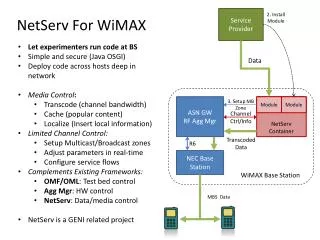
Baseband Architecture Design for Future Wireless Base-Station Receivers. Sridhar Rajagopal April 26, 2000. This work is supported by Nokia, Texas Instruments, Texas Advanced Technology Program and NSF. Outline. Background Multiuser Channel Estimation and Detection

E N D
Baseband Architecture Design for Future Wireless Base-Station Receivers Sridhar Rajagopal April 26, 2000 This work is supported by Nokia, Texas Instruments, Texas Advanced Technology Program and NSF
Outline • Background • Multiuser Channel Estimation and Detection • DSP Implementation and Task Partitioning • Reduced Complexity Algorithms • VLSI Architecture • Architecture/Extensions for DSPs and GPPs
Evolution of Wireless Communications First Generation Voice Second/Current Generation Voice + Low-rate Data (9.6Kbps) Third Generation + Voice + High-rate Data (2 Mbps) + Multimedia W-CDMA
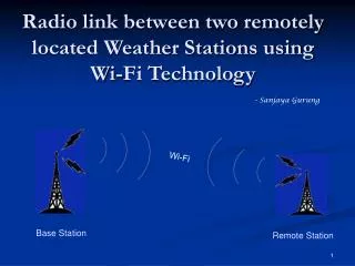
Noise +MAI Base Station Reflected Paths Direct Path User 1 User 2 Communication SystemUplink
Base-station Receiver Antenna Data Multiuser Detection Decoder Detected Bits Delay Decision Feedback Multiple Users + Demod -ulator Channel Estimation d MU X MU X Pilot b Main Processing Blocks Baseband Layer of Base-Station Receiver
Real -Time Requirements • Multiple Data Rates by Varying Spreading Factors • Detection needs to be done in real-time • 1953 cycles available in a C6x DSP at 250MHz to detect 1 bit at 128 Kbps
Outline • Background • Multiuser Channel Estimation and Detection • DSP Implementation and Task Partitioning • Reduced Complexity Algorithms • VLSI Architecture • Architecture/Extensions for DSPs and GPPs
time bi+1 bi ri Channel Model delay • Compute Correlation Matrices Bits of K async. users aligned at times I and I-1 Received bits of spreading length N for K users
Channel Estimation Solve for the channel estimate, Ai Multishot
Differencing Multistage Detection • Stage 0- Matched Filter • Stage 1 • Successive Stages S=diag(AHA) y - soft decision d - detected bits (hard decision)
Structure of AHA Block Bi-Diagonal Matrix
Outline • Background • Multiuser Channel Estimation and Detection • DSP Implementation and Task Partitioning • Reduced Complexity Algorithms • VLSI Architecture • Architecture/Extensions for DSPs and GPPs
4 Data Rate Comparisons for Matched Filter and Multiuser Detector x 10 18 16 14 Targeted Data Rate = 128Kbps 12 10 Projected (8x) Data Rates Achieved 8 Matched Filter(C64)* Multiuser Detector(C64)* 6 Matched Filter(C67) Multiuser Detector(C67) Targeted Data Rate 4 2 C67 at 166MHz 0 9 10 11 12 13 14 15 Number of Users Current DSP Implementation
Reasons for Poor Performance • Sophisticated, Compute-Intensive Algorithms • Need more MIPs/FLOPs performance • Unable to fully exploit pipelining or parallelism • Bit - level computations / Storage
Block I Block III Block II Multistage Detector Correlation Matrices (Per Bit) Inverse Matrix Products Block IV M UX d A0HA1 O(K2N) Multistage Detection (Per Window) RbbAH = Rbr[R] O(K2N) Rbr[R] O(KN) b A0HA0 O(K2N) Rbr[I] O(KN) M UX Data’ RbbAH = Rbr[I] O(K2N) d O(DK2Me) Rbb O(K2) A1HA1 O(K2N) Pilot AHr O(KND) Data Channel Estimation Matched Filter Task Decomposition [Asilomar’99]
x 10 Data Rates for Different Levels of Pipelining and Parallelism 3 2.5 2 Data Rates 1.5 Data Rate Requirement = 128 Kbps 1 0.5 0 9 10 11 12 13 14 15 Number of Users Achieved Data Rates 5
Task Partitioning Hardware Req. • O(K2) processing elements • 1024 for K =32 • Can meet Real-Time • Not feasible in hardware
Outline • Background • Channel Estimation and Detection • DSP Implementation and Task Partitioning • Reduced Complexity Algorithms • VLSI Architecture • Architecture/Extensions for DSPs and GPPs
Iterative Scheme for Estimation • Tracking • Method of Gradient Descent • Stable convergence behavior • Symmetric, Positive Definite Rbb • µ - MAI, SNR, Preamble length • Same Performance
Comparison of Bit Error Rates (BER) -1 10 -2 BER 10 O(K2N) MF ActMF ML ActML O(K3+K2N) -3 10 4 5 6 7 8 9 10 11 12 Signal to Noise Ratio (SNR) Simulations - AWGN Channel Detection Window = 12 SINR = 0 Paths =3 Preamble L =150 Spreading N = 31 Users K = 15 10000 bits/user MF – Matched Filter ML- Maximum Likelihood ACT – using inversion
0 10 MF - Static MF - Tracking ML - Static ML - Tracking -1 10 BER -2 10 -3 10 4 5 6 7 8 9 10 11 12 SNR Fading Channel with Tracking Doppler = 10 Hz, 1000 Bits,15 users, 3 Paths
Pre-computed Preamble • Preamble bits bi known at the receiver • Reduces Complexity, if pre-computed.
Computational Savings in Estimation • Pre-computed Auto-correlation has large savings • Can be used only for quasi-static channels and initial acquisition.
bi-2 bi-1 bi bi+1 User 1 time bi+1 bi Interference from future bits of other users ri Desired User Interference from previous bits of other users User j Pipelined Detection Scheme
Matched Filter 1 12 Stage 1 1 12 Stage 2 1 12 Stage 3 1 12 Matched Filter Bits 2-11 11 22 Stage 1 11 22 Stage 2 11 22 Stage 3 11 22 Bits 12-21 Block Based Detector
1 2 3 4 5 6 7 8 9 10 11 12 1 2 3 4 5 6 7 8 9 10 11 12 1 2 3 4 5 6 7 8 9 10 11 12 1 2 3 4 5 6 7 8 9 10 11 12 Pipelined Detector Matched Filter 1 2 3 4 5 6 7 8 9 10 11 12 Stage 1 Stage 2 Stage 3
Computational Savings in Detection • Edge Bits are not computed • Bit-streaming • Simpler Hardware Structure • 6K2 per Window Savings
Outline • Background • Real-Time Requirements • DSP Implementation and Task Partitioning • Reduced Complexity Algorithms • VLSI Architecture • Architecture/Extensions for DSPs and GPPs
VLSI Implementation [ASAP’2000] • Channel Estimation as a Case Study • Area - Time Efficient Architecture • Real - Time Implementation • Minimum Area Overhead • Bit- Level Computations - FPGAs • Core Operations - DSPs
Area-Time Tradeoffs • Area-Constrained Architecture • Pico-cells ; lower data rates • Time-Constrained Architecture • Maximum achieve-able data rates • Area-Time Efficient Architecture • Real-Time with minimum area overhead
Outline • Background • Channel Estimation and Detection • DSP Implementation and Task Partitioning • Reduced Complexity Algorithms • VLSI Architecture • Architecture/Extensions for DSPs and GPPs
Motivation for Architecture • Wireless, the next wave after Multimedia • Highly Compute-Intensive Algorithms • Real-Time Requirements
Characteristics of Wireless Algorithms • Massive Parallelism • Bit-level Computations • Matrix Based Operations • Memory Intensive • Complex-valued Data • Approximate Computations
Home Area Wireless LAN Outdoor CDMA Cellular Network High Speed Office Wireless LAN Why Reconfigurable • Adapt algorithms to environment • Seamless and Continuous Data Processing during Handoffs
Source Coding Channel Coding Source Decoding Channel Decoding Multiuser Detection Channel Estimation Different Protocols • MPEG-4, H.723 - Voice,Multimedia • Convolutional,Turbo - Channel Coding
A New Architecture Main Memory Processor Core (GPP/DSP) Cache Q Q Crossbar Real-Time I/O Bit Stream Reconfigurable Logic RF Unit Add-on PCMCIA Card Processor
Reconfigurable Support • Configuration Caches • Recently Displaced Configurations (5 cycles) • Can hold 4 full size Configurations • Independent Execution
Permutation Based Interleaved Memory • High Memory Bandwidth Needed • Stride-Insensitive Memory System for Matrices • Randomizes access • Multiple Banks • Sustained Peak Throughput (95%)
Instruction Set Extensions • To accelerate Bit level computations in Wireless • Integer - Bit Multiplications • Multiuser Detection, Decoding, Cross Correlation • Bit - Bit Multiplications • Auto-Correlation, Channel Estimation • Useful in other Signal Processing applications • Speech, Video,,,
64-bit Register A 64-bit Register B 8 8 + + x 8 64-bit Register C SIMD Parallelism
64-bit Register D[i][j] 8 8 +/- +/- 8 8-bit Control Register b[i] 64-bit Register D[i][j] Integer - Bit Multiplications 64-bit Register C[j] For i = 1..8, j= 1..8 D[i][j] = D[i][j] + b[i]*C[j] (Cross-Correlation)
Computational Savings • Avoid bit multiplications and control structures • 4 8-bit Multiply • Latency 3 • 8 8-bit Add • Latency 1 • Cross-Correlation Example • 64 multiply, 64 add
ALU Multipliers Truncated Multiplier Multiplier 1 Multiplier 2 Truncated Multipliers • Many applications need approximate computations • Adaptive Algorithms :Y = Y + mu*(Y*C) • Truncate lower bits • Half the area/half the delay • Can do 2 truncated multiplies in parallel with regular
Future Work • Long Codes - Implementation • Online Arithmetic • Multiprocessing on DSPs and FPGAs
Conclusions • Architecture and Algorithms to meet real-time • Task Decomposition • Real Time with Multiple Processing Elements • Iterative Algorithms • Reduce Complexity, Simpler Implementation • VLSI Implementation • Real-Time with minimum Area Overhead • Architecture/Extensions to DSPs and GPPs