Download
1 / 49
510 likes | 705 Views
Baseband Receiver. Unipolar vs. Polar Signaling Signal Space Representation. Unipolar vs. Polar Signaling. æ. ö. æ. ö. E. æ. ö. 2. E. A. T. ç. ÷. ç. ÷. ç. ÷. =. =. =. b. Q. d. P. Q. Q. ç. ÷. ç. ÷. ç. ÷. b. 2. N. 2. N. 2N. è. ø. è. ø. è. ø. 0. 0. 0.

E N D
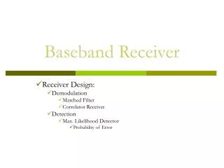
Baseband Receiver Unipolar vs. Polar Signaling Signal Space Representation
æ ö æ ö E æ ö 2 E A T ç ÷ ç ÷ ç ÷ = = = b Q d P Q Q ç ÷ ç ÷ ç ÷ b 2 N 2 N 2N è ø è ø è ø 0 0 0 Error Probability of Binary Signals • Unipolar Signaling
æ ö æ ö æ ö 2 E 4 A T 2 E ç ÷ ç ÷ ç ÷ = = = d b P Q Q Q ç ÷ ç ÷ ç ÷ b 2 N 2 N N è ø è ø è ø 0 0 0 • Polar Signaling (antipodal)
Orthogonal Bipolar ( Antipodal ) æ ö E ç ÷ = b P Q ç ÷ b N è ø 0 • Bipolar signals require a factor of 2 increase in energy compared to Orthagonal • Since 10log102 = 3 dB, we say that bipolar signaling offers a 3 dB better performance than Orthagonal
Error Performance Degradation • Two Types of Error-Performance Degradation • Power degradation • Signal distortion (a) Loss in Eb/No. (b) Irreducible PB caused by distortion.
S6(t) S7(t) S0(t) S1(t) S2(t) S3(t) S4(t) S5(t) 8 Level PAM
(t) 8 Level PAM Then we can represent
8 Level PAM • We can have a single unit height window (t) as the receive filter • And do the decisions based on the value of z(T) • We can have 7 different threshold values for our decision (we have one threshold value for PCM detection) • In this way we can cluster more & more bits together and transmit them as single pulse • But if we want to maintain the error rate then the • transmitted power = f (clustered no of bitsn)
0 (t) S0(t) S1(t) S2(t) S3(t) S4(t) S5(t) S6(t) S7(t) (t) as a unit vector • One dimensional vector space (a Line) • If we assume (t) as a unit vector i, then we can represent signals s0(t) to s7(t) as points on a line (one dimensional vector space)
Signal space • What is a signal space? • Vector representations of signals in an N-dimensional orthogonal space • Why do we need a signal space? • It is a means to convert signals to vectors and vice versa. • It is a means to calculate signals energy and Euclidean distances between signals. • Why are we interested in Euclidean distances between signals? • For detection purposes: The received signal is transformed to a received vectors. The signal which has the minimum distance to the received signal is estimated as the transmitted signal.
Signal space • To form a signal space, first we need to know the inner product between two signals (functions): • Inner (scalar) product: • Properties of inner product: = cross-correlation between x(t) and y(t)
Signal space – cont’d • The distance in signal space is measure by calculating the norm. • What is norm? • Norm of a signal: • Norm between two signals: • We refer to the norm between two signals as the Euclidean distance between two signals. = “length” of x(t)
Signal space - cont’d • N-dimensional orthogonal signal space is characterized by N linearly independent functions called basis functions. The basis functions must satisfy the orthogonality condition where • If all , the signal space is orthonormal. Orthonormal basis • Gram-Schmidt procedure
Signal space – cont’d • Any arbitrary finite set of waveforms where each member of the set is of duration T, can be expressed as a linear combination of N orthonogal waveforms where . where Vector representation of waveform Waveform energy
Signal space - cont’d Waveform to vector conversion Vector to waveform conversion
Schematic example of a signal space Transmitted signal alternatives Received signal at matched filter output
Example of distances in signal space The Euclidean distance between signals z(t) and s(t):
0 0 0 T t Example of an ortho-normal basis functions • Example: 2-dimensional orthonormal signal space • Example: 1-dimensional orthonornal signal space
Example of projecting signals to an orthonormal signal space Transmitted signal alternatives
Implementation of matched filter receiver Bank of N matched filters Observation vector
Bank of N correlators Observation vector Implementation of correlator receiver
0 T t Example of matched filter receivers using basic functions • Number of matched filters (or correlators) is reduced by 1 compared to using matched filters (correlators) to the transmitted signal. • Reduced number of filters (or correlators) T t 0 T t 0 1 matched filter 0 T t
Example 1. 26
(continued) 27
(continued) 28
Notes on Signal Space • Two entirely different signal sets can have the same geometric representation. • The underlying geometry will determine the performance and the receiver structure for a signal set. • In both of these cases we were fortunate enough to guess the correct basis functions. • Is there a general method to find a complete orthonormal basis for an arbitrary signal set? Gram-Schmidt Procedure 30
Gram-Schmidt Procedure Suppose we are given a signal set: We would like to find a complete orthonormal basis for this signal set. The Gram-Schmidt procedure is an iterative procedure for creating an orthonormal basis. 31
Step 1: 37
Step 2: 38
Step 3: * No new basis function 39
Step 4: * No new basis function. Procedure is complete 40
Final Step: 41
Bandpass Signals Representation
Representation of Bandpass Signals Bandpass signals (signals with small bandwidth compared to carrier frequency) can be represented in any of three standard formats: 1. Quadrature Notation s(t) = x(t) cos(2πfct) − y(t) sin(2πfct) where x(t) and y(t) are real-valued baseband signals called the in-phase and quadrature components of s(t) 44
(continued) Complex Envelope Notation where is the complex baseband or envelope of . Magnitude and Phase where is the magnitude of , and is the phase of . 45
Key Ideas from I/QRepresentation of Signals We can represent bandpass signals independent of carrier frequency. The idea of quadrature sets up a coordinate system for looking at common modulation types. The coordinate system is sometimes called a signal constellation diagram. Real part of complex baseband maps to x-axis and imaginary part of complex baseband maps to the y-axis 46
Interpretation of Signal Constellation Diagram • Axis are labeled with x(t) and y(t) • In-phase/quadrature or real/imaginary • Possible signals are plotted as points • Symbol amplitude is proportional to distance from origin • Probability of mistaking one signal for another is related to the distance between signal points • Decisions are made on the received signal based on the distance of the received signal (in the I/Q plane) to the signal points in the constellation
Binary PAM 4-ary PAM 0 0 0 T t For PAM signals How???