Download
1 / 39
410 likes | 451 Views
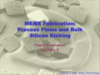
Bulk and SOI MEMS sami.franssila@aalto.fi. sensor material. Pt measurement electrodes. oxide. Nitride. Pt heater. Micro hot plate: how many litho steps ?. 0. Double side polished <100> wafer LPCVD nitride Litho1 on backside for nitride Nitride RIE & resist strip Pt sputter

E N D
Bulk and SOI MEMS sami.franssila@aalto.fi
sensor material Pt measurement electrodes oxide Nitride Pt heater Micro hot plate: how many litho steps ? 0. Double side polished <100> wafer • LPCVD nitride • Litho1 on backside for nitride • Nitride RIE & resist strip • Pt sputter • Litho2 of Pt heater • Pt etch & strip • CVD oxide • Litho3 to reveal Pt heater for wire bond • Oxide etch & strip • Pt sputter • Litho4 of Pt measurement electrodes • Pt etch & resist strip • Frontside protection (jig) • Backside KOH etch • Sensor material depo & patterning
<Si> microbridges Backside micromachining Need front-to-back alignment Bridge thickness free variable May use p++ etch stop May use KOH and/or DRIE Front side micromachining Alignment on front only Needs p++ etch stop Depends on p++ selectivity Needs epi for thick bridge Wider bridge depth under larger
Double side alignment Double sided lithography requires DSP wafers (Double Side Polished) Some alignments are critical but not all ! Often the backside structures are large, and not critically aligned to top side features.
Alignment: diffused piezoresistors OK NOT OK Piezoresistors have to be positioned at the maximum defelection region
Capacitive accelerometer Pyrex glass wafer Capacitor 1 Capacitor 2 Pyrex glass wafer
Pressure sensor deflection Simple membrane Not a parallel plate capacitor Hinged membrane: Parallel plate capacitor
heat sink heater resistor thermopile nitride p1 p0 p0 Thermal pressure sensor
SOI and wet etching Dokmeci 2004 IEEE
AFM tips: thru-wafer • SOI wafer with 5-μm thick device layer • thermal oxidation • LPCVD nitride • etch nitride from front side • lithography for the tip • etch oxide • etch silicon isotropically (+ resist strip) • thermal oxidation for tip-sharpening • lithography to define the cantilever • DRIE of device silicon (+resist strip)
AFM tips: thru-wafer (2) • DRIE of device silicon (+resist strip) • thermal oxidation for passivation • lithography for piezoresistors • boron implantation for resistors (+strip) • lithography & etch for contact • boron implantation for contacts (+ strip) • implant activation in RTA • aluminum deposition and patterning • front protection: polyimide spinning • backside nitride litho & etch & strip • backside TMAH anisotropic etch • buried oxide etching • polyimide plasma removal
Membrane chip with Au/Sn solder bumbs air gap acoustic holes Backplate chip with acoustic holes Bonded microphone
Ogawa, Masuda, Takagawa, Kimata: Polarization-selective uncooled infrared sensor with asymmetric two-dimensional plasmonic absorber Opt. Eng. 53(10), 107110 (2014) Etch selectivity between Si and Al: use TMAH etchant
Ogawa, Masuda, Takagawa, Kimata: Polarization-selective uncooled infrared sensor with asymmetric two-dimensional plasmonic absorber Opt. Eng. 53(10), 107110 Isotropic silicon etch, SF6 plasma, or XeF2, selective against metals.
Surface-bulk combo Microphone with thick silicon backplate
Cavity-SOI (C-SOI) (devicelayer 2 – 50 microns) Thermal oxidation Lithography + ox etch Si DRIE Grind + CMP Direct bonding + anneal
C-SOI specifications Device layer 2 – 50 μm BOX thickness0.2 - 4μm Layer transfer?? Antti make up something cool. Cavity depth1 - 300μm Cavity width 1 - 1200μm ± 10 % Handle wafer 200 - 1000μm
Cavity dimensions vs. SOI thickness Luoto et al. "MEMS on cavity-SOI wafers." Solid-State Electronics 51.2 (2007): 328-332.
C-SOI MEMS Solid-State Electronics 51 (2007) 328–332
oxide Al electrode Si membrane air cavity ground electrode Cavity-SOI resonator • DSP silicon handle wafer • Lithography of air cavity • DRIE of silicon & strip PR • Cleaning • Thermal oxidation • Bonding with a bulk wafer • Thinning by KOH etching • Polishing • Al sputtering • Litho • Al etch & strip • CVD oxide
C-SOI: No need for release etching
C-SOI: alignment • Cavity and otherfront-side structureswillbecoveredbythedevicesilicon • Alignmenthas to bedonewithbacksidetargets. • Backsidetargetcanlaterbetransfered to front.
CMOS-MEMS integrated CMOS first MEMS in silicon MEMS in IC thin films MEMS thin films specifically MEMS first plug-up SOI polysilicon thin film MEMS Integrated processes
b a CMOS first, no additional films a) thin film MEMS by front side dry plasma release; b) single crystal silicon MEMS byDRIE
CMOS-MEMS Piezoresistive Accelerometer Khir Sensors 2011, 11, 7892-7907;
MEMS packaging Capping wafer Thin film sealing
MEMS reliability 1. Solid state devices, no cavities or moving parts. 2. Devices with channels/cavities but no moving parts. 3. Devices with bending/moving but non-contacting parts. 4. Devices with contacting surfaces. 5. Devices with contacting and rubbing surfaces.
MEMS commercialization • Solid state devices, no cavities or moving parts. MAJOR INDUSTRY. 2. Devices with channels/cavities but no moving parts. INK JET PRINTERS
3. Devices with bending/oscillating but non-contacting parts. Pressure sensors Accelerometers Microphones IR detectors cMUTS, pMUTS Widely available.
4. Devices with contacting surfaces. Some available. Wafer level packaging helps a lot. Micromirrors Microvalves RF switches
5. Devices with contacting and rubbing surfaces Gears Turbines Pop-up mirrors None available. Wafer level packaging does not help.
https://media.nature.com/m685/nature-assets/micronano/2015/micronano20155/images_hires/micronano20155-f10.jpghttps://media.nature.com/m685/nature-assets/micronano/2015/micronano20155/images_hires/micronano20155-f10.jpg