Download
1 / 11
110 likes | 130 Views
Learn about IPv4 network layer protocol, IP datagram structure, fragmentation, classes, subnetting, and address hierarchy.

E N D
Network Layer – IPv4 Dr. Sanjay P. Ahuja, Ph.D. Fidelity National Financial Distinguished Professor of CIS School of Computing, UNF
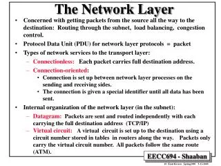
IPv4 • Internet Protocol (IP) is the glue that holds the Internet together. • Communication in the Internet: • Transport Layer takes a data stream and breaks them up into packets (datagrams). • An IP datagram can be up to 64 KB but in practice they are about 1500 bytes. • Each IP datagram is routed through the Internet, possibly being fragmented into smaller units as it goes. • When all the fragments get to the destination machine they are reassembled by the network layer into the original datagram, which is handed to the transport layer.
IPv4 • The IP datagram header has a 20 byte fixed part and a variable length optional part.
IPv4 • Version (4-bits): indicates version of the protocol the datagram belongs to. • IHL (4-bits): This field provides the length of the IP header. The length of the header is represented in 32 bit words. Minimum value = 0101 (i.e. 5) which corresponds to 5 * 4 = 20 bytes. Maximum value = 1111 (i.e. 15) which corresponds to 15 * 4 = 60 bytes. So the options part of the header can be at most 40 bytes. • Differentiated Services (8-bits): Corresponds to type of service. The first 3 bits of this field are priority bits and are ignored as of today. The next 3 bits represent type of service and the last 2 bits are unused. The 3 bits that represent type of service are: minimize delay, maximize throughput, and maximize reliability. • Total Length (16-bits): This represents the total IP datagram length in bytes (header + data). Maximum size = 64 K or 65535 bytes. • Identification (16 bits): Enables the destination host to determine which datagram a newly arrived fragment belongs to. All fragments of a datagram contain the same Identification value.
IPv4 • DF bit (1-bit): Don’t fragment (if destination is incapable of putting a datagram fragments back together). • MF (1-bit): More fragments. All fragments except the last one have this bit set to 1. • Fragment Offset (13-bits): Indicates where in the current datagram this fragment belongs (213 = 8192 fragments per datagram and 8192 * 8 = 65536 bytes. Each fragment is a multiple of 8 bytes) • TTL (8-bits): Used to limit packet lifetime. Maximum lifetime = 255 seconds. In practice, it just counts hops. Default = 64 hops, which is decremented each time the packet is forwarded. • Protocol (8-bits wide): Tells IP which transport protocol to give the datagram to (i.e. TCP or UDP). • Header Checksum (16-bits): Verifies the header. • Source and Destination Addresses (32-bits each): Indicate IP address (network number and host number) of host. • Options (maximum 40-bytes): Presences of options indicated by IHL field. Options include record route, timestamp, and strict source routing.
IP Fragmentation – An Example • MTU: largest IP datagram that can be carried in a frame is called the Max Transmission Unit or MTU • MTU (Ethernet): 1500 bytes • MTU (FDDI): 4500 bytes • MTU (Point-to-point link): 532 bytes (512 bytes data + 20 bytes IP header. Host H1 Router R1 Router R2 Router R3 Host H2 Ethernet FDDI Pt.-to-pt, Ethernet
IP Fragmentation – Example contd. • Un-fragmented Packet: • Fragmented Packets:
IPv4 Address Classes • IP addresses are hierarchical, i.e. made up of 2 parts: a network part and a host part. • Class A: has 7-bits for network part and 24 bits for the host part. There can only be 27 = 128 class A networks and up to 224 – 2 = (16,777,214 or 16 million) hosts. • Class B: 214 = 16,384 class B networks with up to 216 - 2 = 65534 hosts each. • Class C: 221 = 2 million class C networks with up to 28 - 2 = 254 hosts each.
Subnetting • Original intent was that one IP address uniquely identify one physical network. • Subnetting is a way to reduce the total number of network numbers that are assigned. • A network is split into several parts for internal use but still acts like a single network to the outside world. Each part is a subnet. • A company starts with a class B address 128.64.0.0. • The 16-bit host number is split into a 8-bit subnet number and a 8-bit host number. Subnet Mask 1 1 1 1 1 1 1 1 1 1 1 1 1 1 1 1 1 1 1 1 1 1 1 1 00000000 255.255.255.0
Subnetting Subnet Mask 1 1 1 1 1 1 1 1 1 1 1 1 1 1 1 1 1 1 1 1 1 1 1 1 00000000 255.255.255.0 • This split allows 256 – 2 = 254 LANs, each with up to 254 hosts. • All hosts on the same LAN will have the same subnet number. Hosts on the different LANs will share the same network number. • We can think of an address as having three parts: network part, subnet part, and a host part. Subnetting introduces another level of hierarchy into the IP address. • 128.64.1.254 AND 255.255.255.0 = 128.64.1.0 (LAN/Subnet #)