Download

1 / 46
480 likes | 704 Views
Switching and Forwarding Network Layer Part I. Switching and Forwarding Generic Router Architecture Forwarding Tables: Bridges/Layer 2 Switches; VLAN Routers and Layer 3 Switches Forwarding in Layer 3 (Network Layer) Network Layer Functions Network Service Models: VC vs. Datagram

E N D
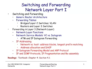
Switching and ForwardingNetwork Layer Part I • Switching and Forwarding • Generic Router Architecture • Forwarding Tables: • Bridges/Layer 2 Switches; VLAN • Routers and Layer 3 Switches • Forwarding in Layer 3 (Network Layer) • Network Layer Functions • Network Service Models: VC vs. Datagram • ATM and IP Datagram Forwarding • IP Addressing • Network vs. host: address blocks, longest prefix matching • Address allocation and DHCP • IP Datagram Forwarding Model and ARP Protocol • IP and ICMP Protocols, IP Fragmentation and Re-assembly Readings: Textbook: Chapter 4: Section 4.1; Forwarding and Routing Network Layer Part I
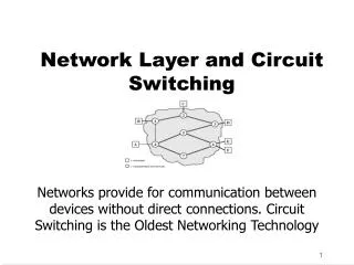
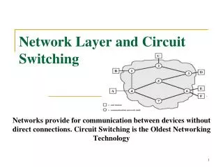
5 3 5 2 2 1 3 1 2 1 F D E B C A Routing & Forwarding:Logical View of a Router Forwarding and Routing Network Layer Part I
Globally unique (for “public” IP addresses) IP address: 32-bit identifier for host, router interface Interface: connection between host/router and physical link router’s typically have multiple interfaces host may have multiple interfaces IP addresses associated with each interface Dot notation (for ease of human reading) 223.1.1.1 = 11011111 00000001 00000001 00000001 223 1 1 1 IP Addressing: Basics Forwarding and Routing Network Layer Part I
Two-level hierarchy network part (high order bits) host part (low order bits) What’s a network ? (from IP address perspective) device interfaces with same network part of IP address can physically reach each other without intervening router 223.1.1.2 223.1.1.1 223.1.1.4 223.1.1.3 223.1.7.0 223.1.9.2 223.1.9.1 223.1.7.1 223.1.8.1 223.1.8.0 223.1.2.6 223.1.3.27 223.1.2.1 223.1.2.2 223.1.3.1 223.1.3.2 IP Addressing: Network vs. Host multi-access LAN point-to-point link Forwarding and Routing Network Layer Part I
7 class 7 15 23 31 1.0.0.0 to 127.255.255.255 A network 0 host 128.0.0.0 to 191.255.255.255 B multicast address 1110 network host 110 192.0.0.0 to 223.255.255.255 C network 10 host 224.0.0.0 to 239.255.255.255 D “Classful” IP Addressing 32 bits • Disadvantage: inefficient use of address space; address space exhaustion • e.g., class B net allocated enough addresses for 65K hosts, even if only 2K hosts in that network Forwarding and Routing Network Layer Part I
host part network part 11001000 0001011100010000 00000000 200.23.16.0/23 Classless Addressing: CIDR CIDR:Classless InterDomain Routing • Network portion of address is of arbitrary length • Addresses allocated in contiguous blocks • Number of addresses assigned always power of 2 • Address format: a.b.c.d/x • x is number of bits in network portion of address Forwarding and Routing Network Layer Part I
Representation of Address Blocks • “Human Readable” address format: a.b.c.d/x • x is number of bits in network portion of address, the network portion is also called the network prefix • machine representation of a network (addr block): using a combination of • first IP of address blocks of the network • network mask ( x “1”’s followed by 32-x “0”’s network w/ address block: 200.23.16.0/23 first IP address of address block: 11001000 0001011100010000 00000000 network mask: 11111111 1111111111111110 00000000 Forwarding and Routing Network Layer Part I
Given an IP address, which network (or address block) does it belong to? Example 1: 11001000 00010111 00010110 10100001 Example 2: 11001000 00010111 00011000 10101010 More Examples Three Address Blocks: First IP address: 11001000 00010111 00010000 00000000 Network mask: 11111111 11111111 11111000 00000000 First IP address: 11001000 00010111 00011000 00000000 Last IP address: 11001000 00010111 00011000 11111111 what is the network prefix? 11001000 00010111 00011000 First IP address: 11001000 00010111 00011001 00000000 Last IP address: 11001000 00010111 00011111 11111111 what is the network prefix? 11001000 00010111 00011 Use longest prefix matching! Forwarding and Routing Network Layer Part I
Another Example • Consider a datagram network using 32-bit host addresses, suppose a router has four links, numbered 0 through 3, and packets are to be forwarded to the link interfaces as follows:Destination Addr Range Link Interface11100000 00000000 00000000 00000000 through 011100000 11111111 11111111 1111111111100001 00000000 00000000 00000000 through 111100001 00000000 11111111 1111111111100001 00000001 00000000 00000000 through 211100001 11111111 11111111 11111111O.W. 3Provide the forwarding table – a table containing the network prefix and the outgoing interface. Forwarding and Routing Network Layer Part I
IP Addresses: How to Get One? Q: How does host get IP address? • “static” assigned: i.e., hard-coded in a file • Wintel: control-panel->network->configuration->tcp/ip->properties • UNIX: /etc/rc.config • Dynamically assigned: using DHCP (Dynamic Host Configuration Protocol) • dynamically get address from a server • “plug-and-play” Forwarding and Routing Network Layer Part I
DHCP: Dynamic Host Configuration Protocol Goal: allow host to dynamically obtain its IP address from network DHCP server when it joins network Can renew its lease on address in use Allows reuse of addresses (only hold address while connected as “on”) Support for mobile users who want to join network (more shortly) DHCP overview: • host broadcasts “DHCP discover” msg • DHCP server responds with “DHCP offer” msg • host requests IP address: “DHCP request” msg • DHCP server sends address: “DHCP ack” msg Forwarding and Routing Network Layer Part I
E B A 223.1.2.1 DHCP 223.1.1.1 server 223.1.1.2 223.1.2.9 223.1.1.4 223.1.2.2 arriving DHCP client needs address in this network 223.1.1.3 223.1.3.27 223.1.3.2 223.1.3.1 DHCP Client-Server Scenario Forwarding and Routing Network Layer Part I
arriving client DHCP server: 223.1.2.5 DHCP offer src: 223.1.2.5, 67 dest: 255.255.255.255, 68 yiaddrr: 223.1.2.4 transaction ID: 654 Lifetime: 3600 secs DHCP request src: 0.0.0.0, 68 dest:: 255.255.255.255, 67 yiaddrr: 223.1.2.4 transaction ID: 655 Lifetime: 3600 secs time DHCP ACK src: 223.1.2.5, 67 dest: 255.255.255.255, 68 yiaddrr: 223.1.2.4 transaction ID: 655 Lifetime: 3600 secs DHCP discover src : 0.0.0.0, 68 dest.: 255.255.255.255,67 yiaddr: 0.0.0.0 transaction ID: 654 DHCP Client-Server Scenario Forwarding and Routing Network Layer Part I
IP Addresses: How to Get One? … Q: How does a network get network part of IP addr? A: gets an allocated portion of its provider ISP’s address space ISP's block 11001000 00010111 00010000 00000000 200.23.16.0/20 Organization 0 11001000 00010111 00010000 00000000 200.23.16.0/23 Organization 1 11001000 00010111 00010010 00000000 200.23.18.0/23 Organization 2 11001000 00010111 00010100 00000000 200.23.20.0/23 ... ….. …. …. Organization 7 11001000 00010111 00011110 00000000 200.23.30.0/23 Forwarding and Routing Network Layer Part I
IP Addressing: the Last Word... Q: How does an ISP get block of addresses? A:ICANN: Internet Corporation for Assigned Names and Numbers • allocates addresses • manages DNS • assigns domain names, resolves disputes Forwarding and Routing Network Layer Part I
NAT: Network Address Translation rest of Internet local network (e.g., home network) 10.0.0/24 10.0.0.1 10.0.0.4 10.0.0.2 138.76.29.7 10.0.0.3 Datagrams with source or destination in this network have 10.0.0/24 address for source, destination (as usual) All datagrams leaving local network have same single source NAT IP address: 138.76.29.7, different source port numbers 10.0.0.0/8 has been reserved for private networks! Forwarding and Routing Network Layer Part I
NAT: Network Address Translation • Motivation: local network uses just one IP address as far as outside world is concerned: • no need to be allocated range of addresses from ISP: - just one IP address is used for all devices • can change addresses of devices in local network without notifying outside world • can change ISP without changing addresses of devices in local network • devices inside local net not explicitly addressable, visible by outside world (a security plus). Forwarding and Routing Network Layer Part I
NAT: Network Address Translation Implementation: NAT router must: • outgoing datagrams:replace (source IP address, port #) of every outgoing datagram to (NAT IP address, new port #) . . . remote clients/servers will respond using (NAT IP address, new port #) as destination addr. • remember (in NAT translation table) every (source IP address, port #) to (NAT IP address, new port #) translation pair • incoming datagrams:replace (NAT IP address, new port #) in dest fields of every incoming datagram with corresponding (source IP address, port #) stored in NAT table Forwarding and Routing Network Layer Part I
2 4 1 3 S: 138.76.29.7, 5001 D: 128.119.40.186, 80 S: 10.0.0.1, 3345 D: 128.119.40.186, 80 1: host 10.0.0.1 sends datagram to 128.119.40, 80 2: NAT router changes datagram source addr from 10.0.0.1, 3345 to 138.76.29.7, 5001, updates table S: 128.119.40.186, 80 D: 10.0.0.1, 3345 S: 128.119.40.186, 80 D: 138.76.29.7, 5001 NAT: Network Address Translation NAT translation table WAN side addr LAN side addr 138.76.29.7, 5001 10.0.0.1, 3345 …… …… 10.0.0.1 10.0.0.4 10.0.0.2 138.76.29.7 10.0.0.3 4: NAT router changes datagram dest addr from 138.76.29.7, 5001 to 10.0.0.1, 3345 3: Reply arrives dest. address: 138.76.29.7, 5001 Forwarding and Routing Network Layer Part I
NAT: Network Address Translation • 16-bit port-number field: • 60,000 simultaneous connections with a single LAN-side address! • NAT is controversial: • routers should only process up to layer 3 • violates end-to-end argument • NAT possibility must be taken into account by app designers, eg, P2P applications • address shortage should instead be solved by IPv6 Forwarding and Routing Network Layer Part I
ICMP protocol • error reporting • router “signaling” Transport layer: TCP, UDP • IP protocol • addressing conventions • packet handling conventions • Routing protocols • path selection • RIP, OSPF, BGP routing table Data Link layer (Ethernet, WiFi, PPP, …) Physical Layer (SONET, …) IP Forwarding & IP/ICMP Protocol Network layer Forwarding and Routing Network Layer Part I
IP Service Model and Datagram Forwarding • Connectionless (datagram-based) • Each datagram carries source and destination • Best-effort delivery (unreliable service) • packets may be lost • packets can be delivered out of order • duplicate copies of a packet may be delivered • packets can be delayed for a long time • Forwarding and IP address • forwarding based on network id • Delivers packet to the appropriate network • Once on destination network, direct delivery using host id • IP destination-based next-hop forwarding paradigm • Each host/router has IP forwarding table • Entries like <network prefix, next-hop, output interface> Forwarding and Routing Network Layer Part I
IP protocol version number 32 bits total datagram length (bytes) header length (32-bit words) type of service head. len ver length for fragmentation/ reassembly fragment offset “type” of data flgs 16-bit identifier max number remaining hops (decremented at each router) upper layer time to live Internet checksum 32 bit source IP address 32 bit destination IP address upper layer protocol to deliver payload to E.g. timestamp, record route taken, specify list of routers to visit. Options (if any) • how much overhead with TCP? • 20 bytes of TCP • 20 bytes of IP • = 40 bytes + app layeroverhead data (variable length, typically a TCP or UDP segment) IP Datagram Format Forwarding and Routing Network Layer Part I
IP datagram: forwarding table in A E B A source IP addr misc fields dest IP addr data 223.1.1.1 223.1.2.1 223.1.1.2 223.1.2.9 223.1.1.4 223.1.2.2 223.1.1.3 223.1.3.27 Dest. Net. next router Nhops 223.1.1 1 223.1.3.2 223.1.3.1 223.1.2 223.1.1.4 2 223.1.3 223.1.1.4 2 IP Datagram Forwarding Model • datagram remains unchanged, as it travels source to destination • addr fields of interest here Forwarding and Routing Network Layer Part I
IP Forwarding Table 4 billion possible entries! (in reality, far less, but can still have millions of “routes”) forwarding table entry format destination networknext-hop (IP address) link interface (1st IP address , network mask ) 11001000 00010111 00010000 00000000, 200.23.16.1 0 11111111 11111111 11111000 00000000 11001000 00010111 00011000 00000000, - (direct) 1 11111111 11111111 11111111 00000000 11001000 00010111 00011001 00000000, 200.23.25.6 2 11111111 11111111 11111000 00000000 otherwise 128.30.0.1 3 Forwarding and Routing Network Layer Part I
Forwarding Table Lookupusing Longest Prefix Matching Prefix MatchNext HopLink Interface 11001000 00010111 00010 200.23.16.10 11001000 00010111 00011000 - 1 11001000 00010111 00011 200.23.25.6 2 otherwise 128.30.0.1 3 Examples Which interface? DA: 11001000 00010111 00010110 10100001 Which interface? DA: 11001000 00010111 00011000 10101010 Forwarding and Routing Network Layer Part I
forwarding table in A B E A 223.1.1.1 223.1.2.1 223.1.1.2 223.1.2.9 223.1.1.4 223.1.2.2 223.1.1.3 223.1.3.27 Dest. Net. next router Nhops 223.1.1 1 223.1.3.2 223.1.3.1 223.1.2 223.1.1.4 2 223.1.3 223.1.1.4 2 IP Forwarding: Destination in Same Net misc fields data 223.1.1.1 223.1.1.3 • Starting at A, send IP datagram addressed to B: • look up net. address of B in forwarding table • find B is on same net. as A • link layer will send datagram directly to B inside link-layer frame • B and A are directly connected Forwarding and Routing Network Layer Part I
223.1.1.1 223.1.2.1 E B A 223.1.1.2 223.1.2.9 223.1.1.4 223.1.2.2 223.1.3.27 223.1.1.3 223.1.3.2 223.1.3.1 frame source, dest address datagram source, dest address A’s IP addr B’s IP addr B’s MAC addr A’s MAC addr IP payload datagram frame IP Datagram Forwarding on Same LAN:Interaction of IP and data link layers • Starting at A, given IP datagram addressed to B: • look up net. address of B, find B on same net. as A • link layer send datagram to B inside link-layer frame Forwarding and Routing Network Layer Part I
MAC (Physical) Addresses -- Revisited • used to get frames from one interface to another physically-connected interface (same physical network, i.e., p2p or LAN) • 48 bit MAC address (for most LANs) • fixed for each adaptor, burned in the adapter ROM • MAC address allocation administered by IEEE • 1st bit: 0 unicast, 1 multicast. • all 1’s : broadcast • MAC flat address -> portability • can move LAN card from one LAN to another • MAC addressing operations on a LAN: • each adaptor on the LAN “sees” all frames • accept a frame if dest. MAC address matches its own MAC address • accept all broadcast (MAC= all1’s) frames • accept all frames if set in “promiscuous” mode • can configure to accept certain multicast addresses (first bit = 1) Forwarding and Routing Network Layer Part I
MAC vs. IP Addresses 32-bit IP address: • network-layer address, logical • i.e., not bound to any physical device, can be re-assigned • IP hierarchical address NOT portable • depends on IP network to which an interface is attached • when move to another IP network, IP address re-assigned • used to get IP packets to destination IP network • Recall how IP datagram forwarding is performed • IP network is “virtual,” actually packet delivery done by the underlying physical networks • from source host to destination host, hop-by-hop via IP routers • over each link, different link layer protocol used, with its own frame headers, and source and destination MAC addresses • Underlying physical networks do not understand IP protocol and datagram format! Forwarding and Routing Network Layer Part I
Question: how to determine MAC address of B knowing B’s IP address? ARP: Address Resolution Protocol • Each IP node (host, router) on LAN has ARP table • ARP Table: IP/MAC address mappings for some LAN nodes < IP address; MAC address; timer> • timer: time after which address mapping will be forgotten (typically 15 min) Forwarding and Routing Network Layer Part I
A wants to send datagram to B, and A knows B’s IP address. A looks up B’s MAC address in its ARP table Suppose B’s MAC address is not in A’s ARP table. A broadcasts (why?) ARP query packet, containing B's IP address all machines on LAN receive ARP query B receives ARP packet, replies to A with its (B's) MAC address frame sent to A’s MAC address (unicast) A caches (saves) IP-to-MAC address pair in its ARP table until information becomes old (times out) soft state: information that times out (goes away) unless refreshed ARP is “plug-and-play”: nodes create their ARP tables without intervention from net administrator ARP Protocol Forwarding and Routing Network Layer Part I
ARP Messages Hardware Address Type: e.g., Ethernet Protocol address Type: e.g., IP Operation: ARP request or ARP response Forwarding and Routing Network Layer Part I
ARP Request & Response Processing • The requesterbroadcasts ARP request • The target nodeunicasts (why?) ARP reply to requester • With its physical address • Adds the requester into its ARP table (why?) • On receiving the response, requester • updates its table, sets timer • Other nodes upon receiving the ARP request • Refresh the requester entry if already there • No action otherwise (why?) • Some questions to think about: • Shall requester buffer IP datagram while performing ARP? • What shall requester do if never receive any ARP response? Forwarding and Routing Network Layer Part I
ARP Operation Illustration Forwarding and Routing Network Layer Part I
forwarding table in A misc fields data 223.1.1.1 223.1.2.3 B A E 223.1.1.1 223.1.2.1 223.1.1.2 223.1.2.9 223.1.1.4 223.1.2.2 223.1.1.3 223.1.3.27 Dest. Net. next router Nhops 223.1.1 1 223.1.3.2 223.1.3.1 223.1.2 223.1.1.4 2 223.1.3 223.1.1.4 2 IP Forwarding: Destination in Diff. Net • Starting at A, dest. E: • look up network address of E in forwarding table • E on different network • A, E not directly attached • routing table: next hop router to E is 223.1.1.4 • link layer sends datagram to router 223.1.1.4 inside link-layer frame • datagram arrives at 223.1.1.4 • continued….. Forwarding and Routing Network Layer Part I
forwarding table in router Dest. Net router Nhops interface misc fields data 223.1.1.1 223.1.2.3 B A E 223.1.1 - 1 223.1.1.4 223.1.2 - 1 223.1.2.9 223.1.3 - 1 223.1.3.27 223.1.1.1 223.1.2.1 223.1.1.2 223.1.2.9 223.1.1.4 223.1.2.2 223.1.1.3 223.1.3.27 223.1.3.2 223.1.3.1 IP Forwarding: Destination in Diff. Net … • Arriving at 223.1.4, destined for 223.1.2.2 • look up network address of E in router’s forwarding table • E on same network as router’s interface 223.1.2.9 • router, E directly attached • link layer sends datagram to 223.1.2.2 inside link-layer frame via interface 223.1.2.9 • datagram arrives at 223.1.2.2!!! (hooray!) Forwarding and Routing Network Layer Part I
Forwarding to Another LAN:Interaction of IP and Data Link Layer walkthrough: send datagram from A to B via R assume A knows B IP address • Two ARP tables in router R, one for each IP network (LAN) • In routing table at source host, find router 111.111.111.110 • In ARP table at source, find MAC address E6-E9-00-17-BB-4B, etc A R B Forwarding and Routing Network Layer Part I
B • A creates datagram with source A, destination B • A uses ARP to get R’s MAC address for 111.111.111.110 • A creates link-layer frame with R's MAC address as dest, frame contains A-to-B IP datagram • A’s data link layer sends frame • R’s data link layer receives frame • R removes IP datagram from Ethernet frame, sees its destined to B • R uses ARP to get B’s physical layer address • R creates frame containing A-to-B IP datagram sends to B A R Forwarding and Routing Network Layer Part I
IP protocol version number 32 bits total datagram length (bytes) header length (bytes) type of service head. len ver length for fragmentation/ reassembly fragment offset “type” of data flgs 16-bit identifier max number remaining hops (decremented at each router) upper layer time to live Internet checksum 32 bit source IP address 32 bit destination IP address upper layer protocol to deliver payload to E.g. timestamp, record route taken, specify list of routers to visit. Options (if any) • how much overhead with TCP? • 20 bytes of TCP • 20 bytes of IP • = 40 bytes + app layeroverhead data (variable length, typically a TCP or UDP segment) IP Datagram Format Again Forwarding and Routing Network Layer Part I
Fields in IP Datagram • IP protocol version: current version is 4, IPv4, new: IPv6 • Header length: number of 32-bit words in the header • Type of Service: • 3-bit priority,e.g, delay, throughput, reliability bits, … • Total length: including header (maximum 65535 bytes) • Identification: all fragments of a packet have same identification • Flags: don’t fragment, more fragments • Fragment offset: where in the original packet (count in 8 byte units) • Time to live: maximum life time of a packet • Protocol Type: e.g., ICMP, TCP, UDP etc • IP Option: non-default processing, e.g., IP source routing option, etc. Forwarding and Routing Network Layer Part I
network links have MTU (maximum transmission unit) - largest possible data gram. different link types, different MTUs large IP datagram divided (“fragmented”) within net one datagram becomes several datagrams “reassembled” only at final destination IP header bits used to identify, order related fragments IP Fragmentation & Reassembly: Why fragmentation: in: one large datagram out: 3 smaller datagrams reassembly Forwarding and Routing Network Layer Part I
IP Fragmentation & Reassembly: How • An IP datagram is chopped by a router into smaller pieces if • datagram size is greater than network MTU • Don’t fragment option is not set • Each datagram has unique datagram identification • Generated by source hosts • All fragments of a packet carry original datagram id • All fragments except the last have more flag set • Fragment offset and Length fields are modified appropriately • Fragments of IP packet can be further fragmented by other routers along the way to destination ! • Reassembly only done at destination host (why?) • Use IP datagram id, fragment offset, fragment flags. Length Forwarding and Routing Network Layer Part I
length =1500 length =1500 length =4000 length =1040 ID =x ID =x ID =x ID =x fragflag =1 fragflag =1 fragflag =0 fragflag =0 offset =0 offset =185 offset =370 offset =0 One large datagram becomes several smaller datagrams IP Fragmentation and Reassembly: Exp • Example • 4000 byte datagram • MTU = 1500 bytes Forwarding and Routing Network Layer Part I
used by hosts, routers, gateways to communicate network-level information error reporting: unreachable host, network, port, protocol echo request/reply (used by ping) network-layer “above” IP: ICMP msgs carried in IP datagrams ICMP message: type, code plus first 8 bytes of IP datagram causing error ICMP: Internet Control Message Protocol TypeCodedescription 0 0 echo reply (ping) 3 0 dest. network unreachable 3 1 dest host unreachable 3 2 dest protocol unreachable 3 3 dest port unreachable 3 6 dest network unknown 3 7 dest host unknown 4 0 source quench (congestion control - not used) 8 0 echo request (ping) 9 0 route advertisement 10 0 router discovery 11 0 TTL expired 12 0 bad IP header Forwarding and Routing Network Layer Part I
ICMP Message Transport & Usage • ICMP messages carried in IP datagrams • Treated like any other datagrams • But no error message sent if ICMP message causes error • Message sent to the source • 8 bytes of the original header included • ICMP Usage (non-error, informational): Examples • Testing reachability: ICMP echo request/reply • ping • Tracing route to a destination: Time-to-live field • traceroute • Path MTU discovery • Don’t fragment bit • IP direct (for hosts only): inform hosts of better routes Forwarding and Routing Network Layer Part I