Download
1 / 21
210 likes | 215 Views
Design of high density SiP. for complex computing system in micro SD format. Chris BARRATT Insight SiP Sophia Antipolis FRANCE. FRANCE. Agenda. “From Sketch to Product”. Introduction Design Process Functional Specification Architecture Component Choice Size versus Component Choice

E N D
Design of high density SiP for complex computing system in micro SD format Chris BARRATT Insight SiP Sophia Antipolis FRANCE FRANCE
Agenda “From Sketch to Product” • Introduction • Design Process • Functional Specification • Architecture • Component Choice • Size versus Component Choice • Detailed Schematic • Breadboard • Substrate Technology • Layout • Electromagnetic Simulation • Assembly • Test and Debug • Micro SD Linux Computer
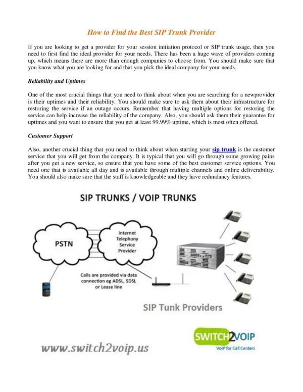
Introduction • The Challenge • How to fit a microprocessor and some memory • Inside a Smart Phone • Sorry How to fit a Linux Computer • Inside a Smart Phone
Functional Specification • Must Fit inside a Smart Phone • Must use micro SD slot • Size 11 x 15 x 1 mm • Interface to Phone via SD interface • Sufficient RAM to run Linux • Sufficient Storage to hold Linux image and programs • Operates from SD power supply • Time to Market • RAM 512MB • Flash 8 GB • MPU • Access via SD port • Runs off 3V from SD
Architecture • Architecture Choices • Meet Functional specifications • Choose off the shelf components (Time to Market) • Consider solutions which have Linux implementations 2.7V in 3.3V out 1.8V out 1.2V out
Component Choice • Criteria • Wafers or WLCSP must be available • NDA process essential • Negotiate with Chip Vendors on a project by project basis • Need to obtain wafer data early to make decisions • Die sizes must be compatible with Micro SD footprint • Must meet architecture requirements • Ideally need EVK with working software stacks for a “breadboard” • Thickness of WLCSP and SMTs must be compatible with Micro SD (< 0.5 mm) MPU SD Client Memories Flash Controller Power Supply
Size vs Component Choice • Evaluate Assembly Options • For each Option estimate size • Choose best compromise • Solution adopted • 4 die Wire Bond Memory stack • LPDDR2 + 2 NAND Flash • Flash Controller on LPDDR2 • 2 die WB stack MPU On FPGA • 4 WLCSP power supply components • 40 SMT Chips (01005, 0201,..)
DetailedSchematic • Create a detailed schematic • 2 versions are required • Breadboard with packaged components • SiP design with bare die components • Optimization of Power supply and decoupling is crucial to fit inside small footprint • Reduce number of passives from 80 to 40 • Power supply components need to be very small
Breadboard • Same schematic as SiP • Uses Packaged components • Based on MPU EVK • Allows first level Hardware Debug • Allows Firmware Development to be essentially in parallel with SiP Hardware • Can be used in SiP debug as reference
SubstrateTechnology • Requirements • Wire-bond capable • 100um wire bond finger pitch • Complex routing 6 layers • Fine line 30um / 30 um • Rear side contacts Hard gold • As thin as possible <=0.25mm • Lowest cost option • Solution • 6 layer any layer to any layer • Electrolytic gold • Complex plating (buss bar ruled out) • using 9 process steps • Pushing limits for etched technology • Overall substrate very thin (0.22mm)
Module Layout • Schematic to Layout • Tool-sets • Cadence Allegro SIP • Mentor Graphics Xpedition Package Integrator • Keysight ADS • Altium PCB • Other PCB tools Capability COST 2D Routing 3D View
Module Technologies • Die Stacking • 3 dies in < 0.58 mm height • Die thickness 60 – 80 um • Film on Wire • Low loop heights • Same die size stack • Wire-bonding • 4 layers of wire bonding • Accurate x y z control to avoid shorts • Small actives • WLCSP <0.5mm • DFN < 0.4 mm • Passives • 01005 mostly • 0201 > 100nF • 0402 > 2 uF • 0603 low profile for DC:DC chokes
Electromagnetic Simulation • Toolset • Keysight ADS Momentum 2.5D / full 3D FEM • Ansys HFSS full 3D EM • Substrate Simulation • Multi-port s parameters (> 100 ports) • High speed track impedances • Coupling between power supply and high speed signals • Effectiveness of decoupling methods (mix EM/Schematic models) • Iterative process • Avoids major failures at first prototype phase • Can be used to fine tune second spin (if needed) Evaluation of Effects in Schematic 2.5D simulation of Layout
SiPAssembly • Courtesy of Amkor • SMT placement and reflow • Sequential Die attach – Wire bond • Accurate 3D wire control • Over-molding • Requires DOE to setup process • Electrical Prototype yield > 95%
DebugProcess • Assumes Breadboard is fully functional • Using Test Board and Socket • Power Up and Validate Power supplies • Program MPU with boot sequence and Linux Kernel via JTAG • Program FPGA with code • Initialize Flash Controller via MPU • Boot from Flash • At each step issues can arise • Compare output with breadboard • Attempt to put breadboard into same failure mode as SiP • Attempt to change SMTs in SiP (accurate diamond drilling) • Example • Issues with assembly spins 1 & 2 was linked to an un-calibrated die and component labelling!!! • Spin 3 using same substrate is fully functional
Micro SD Power Supplies • 2 Step down power supplies • 1.2V, 1.8V • 1 step up power supply • 3.3V from 2.7V • 1 power supply monitor • Detect under voltage
Memory Stacking • LPDDR2 • Wirebonds N&S • Flash controller • Wirebonds W • Nand Flash • Wirebonds E • Total Thickness < 0.5mm • Total 250 wirebonds Flash Ctrl Nand x 2 LPDDR2 Nand x 2 Flash Ctrl LPDDR2
MPU on FPGA • FPGA • Wire-bonds on 2 rows on 4 sides • Die is smaller than MPU • FPGA is under MPU • 191 Wire-bonds • MPU • Wire-bonds on 2 rows on 4 sides • Die is bigger than FPGA • MPU is on top • 314 Wire-bonds MPU FPGA
Conclusions • Design Process for Complex SiP has been demonstrated • Uses State of the Art « Mainstream » technologies • Avoids the use of expensive tool-sets • Avoids the use of unproven technologies • Heterogeneous SiP for medium volume requires a conservative approach • The Example micro SD SiP is probably smallest Linux computer today