Download
1 / 20
200 likes | 387 Views
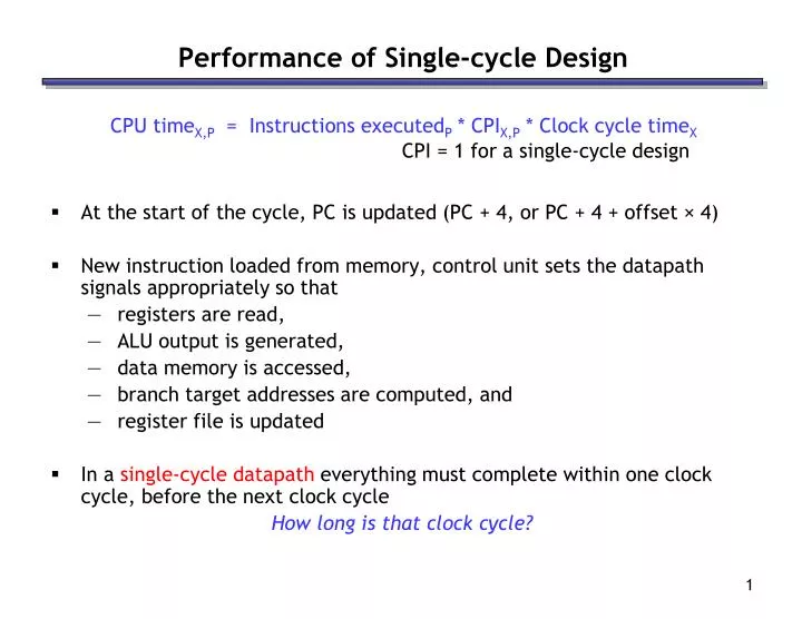
Performance of Single-cycle Design. At the start of the cycle, PC is updated (PC + 4, or PC + 4 + offset × 4) New instruction loaded from memory, control unit sets the datapath signals appropriately so that registers are read, ALU output is generated, data memory is accessed,

E N D
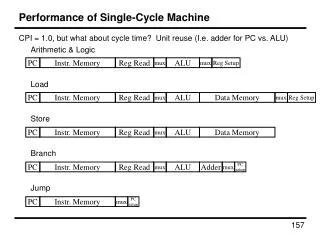
Performance of Single-cycle Design • At the start of the cycle, PC is updated (PC + 4, or PC + 4 + offset × 4) • New instruction loaded from memory, control unit sets the datapath signals appropriately so that • registers are read, • ALU output is generated, • data memory is accessed, • branch target addresses are computed, and • register file is updated • In a single-cycle datapath everything must complete within one clock cycle,before the next clock cycle How long is that clock cycle? CPU timeX,P = Instructions executedP * CPIX,P * Clock cycle timeX CPI = 1 for a single-cycle design
1 M u x 0 reading the instruction memory 2ns reading the register file 1ns ALU computation 2ns accessing data memory 2ns writing to the register file 1ns I [25 - 21] 8ns Read address Instruction [31-0] Read register 1 Read data 1 ALU Read address Read data I [20 - 16] Zero Read register 2 Instruction memory Read data 2 Result Write address 0 M u x 1 0 M u x 1 Write register Data memory Write data Registers I [15 - 11] Write data Sign extend I [15 - 0] Components of the data-path • Each component of the datapath has an associated delay (latency) • The cycle time has to be large enough to accommodate the slowest instruction 2 ns 2 ns 0 ns 2 ns 0 ns 0 ns 1 ns 0 ns
How bad is this? • With these same component delays, a sw instruction would need 7ns, and beq would need just 5ns • Let’s consider the gcc instruction mix: • With a single-cycle datapath, each instruction would require 8ns • But if we could execute instructions as fast as possible, the average time per instruction for gcc would be: (48% x 6ns) + (22% x 8ns) + (11% x 7ns) + (19% x 5ns) = 6.36ns • The single-cycle datapath is about 1.26 times slower!
Improving performance • Two ideas for improving performance: • Spilt each instruction into multiple steps, each taking 1 cycle • steps: IF (instruction fetch), ID (instruction decode), EX (execute ALU operation), MEM (memory access), WB (register write-back) • slow instructions take more cycles than fast instructions • known as a multi-cycle implementation • Crucial observation: each instruction uses only a portion of the datapath in each step • can overlap instructions; each uses one portion of the datapath • known as a pipelined implementation • Examples of pipelining: any assembly process (cars, sandwiches), multiple loads of laundry (washer + dryer can be pipelined), etc.
ORD TOS ADD PAY ORD TOS ADD PAY ORD TOS ADD PAY 0 10 20 30 40 50 60 Pipelining: Example • Assembling a sandwich: Order, Toast (optional), Add extras, Pay • ORD (8 seconds) • TOS (0 or 10 seconds) • ADD (0 to 10 seconds) • PAY (5 seconds) • We can assemble sandwiches every 10 seconds with pipelining: A single sandwich takes between 13 and 33 seconds
Pipelining lessons • Pipelining can increase throughput (#sandwiches per hour), but… • Every sandwich must use all stages • prevents clashes in the pipeline • Every stage must take the same amount of time • limited by the slowest stage (in this example, 10 seconds) • These two factors decrease the latency (time per sandwich)! • For an optimal k-stage pipeline: • every stage does useful work • stage lengths are balanced • Under these conditions, we nearly achieve the optimal speedup: k • “nearly” because there is still the fill and drain time
Pipelining not just Multiprocessing • Pipelining does involve parallel processing, but in a specific way • Both multiprocessing and pipelining relate to the processing of multiple “things” using multiple “functional units” • In multiprocessing, each thing is processed entirely by a single functional unit • e.g. multiple lanes at the supermarket • In pipelining, each thing is broken into a sequence of pieces, where each piece is handled by a different (specialized) functional unit • e.g. checker vs. bagger • Pipelining and multiprocessing are not mutually exclusive • Modern processors do both, with multiple pipelines (e.g. superscalar) • Pipelining is a general-purpose efficiency technique; used elsewhere in CS: • Networking, I/O devices, server software architecture
Pipelining MIPS • Executing a MIPS instruction can take up to five stages • Not all instructions need all five stages and stages have different lengths • Clock cycle time determined by length of slowest stage (2ns here)
RegWrite MemToReg MemWrite Read address Instruction [31-0] I [25 - 21] Read register 1 Read data 1 ALU Read address Read data 1 M u x 0 I [20 - 16] Zero Read register 2 Instruction memory Read data 2 0 M u x 1 Result Write address 0 M u x 1 Write register Data memory Write data Registers I [15 - 11] ALUOp Write data MemRead ALUSrc RegDst I [15 - 0] Sign extend Instruction Fetch (IF) • While IF is executing, the rest of the datapath is sitting idle…
RegWrite MemToReg MemWrite Read address Instruction [31-0] I [25 - 21] Read register 1 Read data 1 ALU Read address Read data 1 M u x 0 I [20 - 16] Zero Read register 2 Instruction memory Read data 2 0 M u x 1 Result Write address 0 M u x 1 Write register Data memory Write data Registers I [15 - 11] ALUOp Write data MemRead ALUSrc RegDst I [15 - 0] Sign extend Instruction Decode (ID) • Then while ID is executing, the IF-related portion becomes idle…
RegWrite MemToReg MemWrite Read address Instruction [31-0] I [25 - 21] Read register 1 Read data 1 ALU Read address Read data 1 M u x 0 I [20 - 16] Zero Read register 2 Instruction memory Read data 2 0 M u x 1 Result Write address 0 M u x 1 Write register Data memory Write data Registers I [15 - 11] ALUOp Write data MemRead ALUSrc RegDst I [15 - 0] Sign extend Execute (EX) • ..and so on for the EX portion…
RegWrite MemToReg MemWrite Read address Instruction [31-0] I [25 - 21] Read register 1 Read data 1 ALU Read address Read data 1 M u x 0 I [20 - 16] Zero Read register 2 Instruction memory Read data 2 0 M u x 1 Result Write address 0 M u x 1 Write register Data memory Write data Registers I [15 - 11] ALUOp Write data MemRead ALUSrc RegDst I [15 - 0] Sign extend Memory (MEM) • …the MEM portion…
Writeback (WB) • …and the WB portion • What about the “clash” with the IF stage over the register file? • Answer: Register file is written on the positive edge, but read later in the clock cycle. Hence, there is no clash RegWrite MemToReg MemWrite Read address Instruction [31-0] I [25 - 21] Read register 1 Read data 1 ALU Read address Read data 1 M u x 0 I [20 - 16] Zero Read register 2 Instruction memory Read data 2 0 M u x 1 Result Write address 0 M u x 1 Write register Data memory Write data Registers I [15 - 11] ALUOp Write data MemRead ALUSrc RegDst I [15 - 0] Sign extend
RegWrite MemToReg MemWrite Read address Instruction [31-0] I [25 - 21] Read register 1 Read data 1 ALU Read address Read data 1 M u x 0 I [20 - 16] Zero Read register 2 Instruction memory Read data 2 0 M u x 1 Result Write address 0 M u x 1 Write register Data memory Write data Registers I [15 - 11] ALUOp Write data MemRead ALUSrc RegDst I [15 - 0] Sign extend Decoding and fetching together • Why don’t we go ahead and fetch the next instruction while we’re decoding the first one? Fetch 2nd Decode 1st instruction
RegWrite MemToReg MemWrite Read address Instruction [31-0] I [25 - 21] Read register 1 Read data 1 ALU Read address Read data 1 M u x 0 I [20 - 16] Zero Read register 2 Instruction memory Read data 2 0 M u x 1 Result Write address 0 M u x 1 Write register Data memory Write data Registers I [15 - 11] ALUOp Write data MemRead ALUSrc RegDst I [15 - 0] Sign extend Executing, decoding and fetching • Similarly, once the first instruction enters its Execute stage, we can go ahead and decode the second instruction • But now the instruction memory is free again, so we can fetch the third instruction! Fetch 3rd Execute 1st Decode 2nd
Break datapath into 5 stages • Each stage has its own functional units • Full pipeline the datapath is simultaneously working on 5 instructions! IF WB ID EXE MEM RegWrite MemToReg MemWrite Read address Instruction [31-0] I [25 - 21] Read register 1 Read data 1 ALU Read address Read data 1 M u x 0 I [20 - 16] Zero Read register 2 Instruction memory Read data 2 0 M u x 1 Result Write address 0 M u x 1 Write register Data memory Write data Registers I [15 - 11] ALUOp Write data MemRead ALUSrc RegDst I [15 - 0] Sign extend newest oldest
A pipeline diagram • A pipeline diagram shows the execution of a series of instructions • The instruction sequence is shown vertically, from top to bottom • Clock cycles are shown horizontally, from left to right • Each instruction is divided into its component stages • Example: In cycle 3, there are three active instructions: • The “lw” instruction is in its Execute stage • Simultaneously, the “sub” is in its Instruction Decode stage • Also, the “and” instruction is just being fetched
Pipeline terminology • The pipeline depth is the number of stages—in this case, five • The pipeline is filling in the first four cycles (unused functional units) • In cycle 5, the pipeline is full. Five instructions are being executed simultaneously, so all hardware units are in use • In cycles 6-9, the pipeline is emptying/draining filling full emptying
Pipelining Performance • How many cycles to execute N instructions on a k stage pipeline? • Solution 1: k 1 cycles to fill the pipeline + one cycle per instruction = k 1 + N cycles • Solution 2: k cycles for the first instruction + one cycle for each of the remaining N 1 instructions • When N = 1000, how much faster is a 5-stage pipeline (2ns clock cycle) vs. a single cycle implementation (8ns clock cycle)? filling
Pipeline Datapath: Resource Requirements • We need to perform several operations in the same cycle • Increment the PC and add registers at the same time • Fetch one instruction while another one reads or writes data • What does that mean for our hardware? • Separate ADDER and ALU • Two memories (instruction memory and data memory)