Download
1 / 22
230 likes | 262 Views
The New Layout Solution for Analog and Mixed Signal Design. Oct 29, 2007 思源科技 產品二處 資深處長 白 錫鴻. IC 設計及製造流程. Wafer (Hundreds of dies). Idea. Block Diagram. Architecture Design. Circuit & Layout Design. Layout. IC Fabrication. Package& Testing. System Manufacture.

E N D
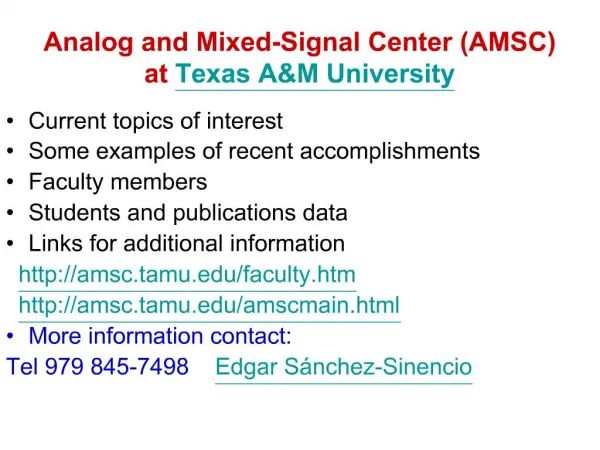
The New Layout Solution for Analog and Mixed Signal Design Oct 29, 2007 思源科技 產品二處 資深處長白錫鴻
IC 設計及製造流程 Wafer (Hundreds of dies) Idea Block Diagram Architecture Design Circuit & Layout Design Layout IC Fabrication Package& Testing System Manufacture
晶片佈局圖(Layout)與實現方法 數位邏輯設計及佈局 RTL Design & Synthesis Simulation Console LakerWave Common Database Floor plan & Prototyping Layout Editor Placement & Route Schematic Editor 客製化線路設計及佈局 Digital P&R Analog module SRAM AD/DAC
Today’s Industry Problems Gates or Analog Transistors per Hour* Huge productivity gap 100,000 10,000 1,000 100 10 Digital Flow: Schematic Synthesis Integrated Flows 3rd Party IP Virtual Prototype Analog Flow: Schematic No Change SPICE PCells No Change • Analog layout not automated • Mostly handcrafted – slow & error prone with complex rules • Prevent early parasitic extraction for simulation • Design time for a new analog block is large due to the lack of reuse scheme • Growing design complexity • 90nm, 65nm, and 45nm • Complex design rule • Parasitic behavior complexity, thermal and process variations, and noise interactions • DFM constraints • Analog design productivity lags digital • Lack of a breakthrough on productivity of custom design *Sources: ITRI Next generation analog and mixed signal design forum
Influence Factors on Layout Productivity & Quality • Engineer experience • Design difficulty • Effective communication between designer and layout engineer • Tools • Easy of use • Powerful features • Layout Solution
Layout Solution -- Polygon Pushing • Strength • Flexibility • Optimum layout result • Issues • Worst productivity • Prone to DRC/LVS error
Layout Solution -- SDL (Schematic-Driven) • Strength • Connectivity from design to minimize LVS error • Design topology awareness from schematic to minimize communication mistake • Better productivity than polygon pushing • Challenges • Powerful device model • Flexibility on design hierarchical management
Powerful Devices Model -- Magic Cell (1) Create Magic cell with single gate Create Magic cell with multi-gate Create Magic cell with different pattern Create Magic cell with different structure Easy to Create Design Rule Correct Devices
Merge Gate Split Gate Insert Gate Subduce Gate Before Before Before Before After After After After Powerful Devices Model -- Magic Cell (2)
Vision on Design Driven Layout Flow Constraint Editor Schematic Entry Circuit Simulation Simulation Interface Designer Constraint Optional Automatic Partition Constraint Simulation Results Automatic Prototyping view Custom Layout Prototyping Simulation Post Layout Simulation DRC/LVS RC Extraction
Layout Solution -- DDL (Design-Driven) • Strength • Extract design constraints from design and simulation result • Unify design and constraint DB to minimize design communication between designer and layout engineer • Constraint driven custom device placement and wire routing
CMOS LAYOUT CASE STUDY >>OP1 NW OD P+ N+ P1 P2 CO M1 M2 VIA
CMOS LAYOUT CASE STUDY >>OP2 4 4 2 3 4 5 6 IP NW OD IN 1 4 P+ 3 N+ P1 6 5 P2 CO M1 M2 VIA 8 7 7 8
Constraint Extraction (1/2) • Extract Matching device constraints for MOSFETs • Examples:
Constraint Extraction (2/2) M2 M1 M6 M5 M9 M7 M10 M8 M11 • Extract symmetry device constraints for MOSFETs • Examples Self-Symmetry
Constraint Editor and Extractor • Auto extract matching and symmetry constraints • Manage and adjust constraints interactively
Matching Device Creator • Routing style – backbone, cross route, … • Comprehensive creation and editing capability
Matching Device Window - Preview • Reduce create Placement iteration
Custom Placer – Transistor Based • Honor Placement Constraints • Support Incremental Placement
Layout Solutions For Custom Design Schematic-Driven Design-Driven Schematic-driven Design-driven Polygon-pushing Rule-Driven Rule-driven Polygon editing Viewing
Summary on Layout Solution Quality • Constraint Extractor • Custom Placer & Router • DRC Rule-driven • P2P • Powerful Devices Model • Hierarchical Manipulation • Issues • Prepare Parameterized cell • Lack of flexibility • Non-optimized Area • Issues • Tedious constraint preparation • Inconsistent constraints between design and layout • Issues • Time Consuming • Error Prone Polygon Pushing Schematic Driven Design Driven Productivity