Download
1 / 41
410 likes | 605 Views
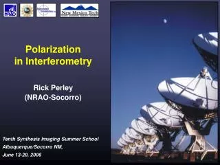
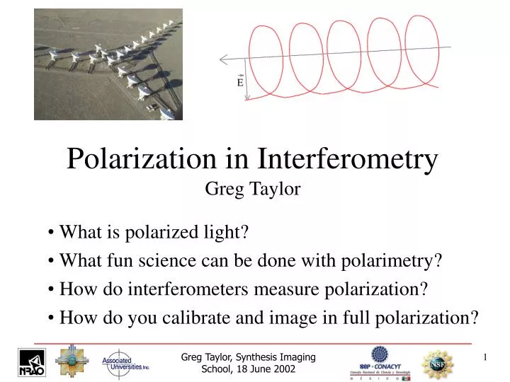
Polarization in Interferometry Greg Taylor. What is polarized light? What fun science can be done with polarimetry? How do interferometers measure polarization? How do you calibrate and image in full polarization?. What is Polarized Light?.

E N D
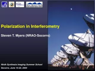
Polarization in InterferometryGreg Taylor What is polarized light? What fun science can be done with polarimetry? How do interferometers measure polarization? How do you calibrate and image in full polarization? Greg Taylor, Synthesis Imaging School, 18 June 2002
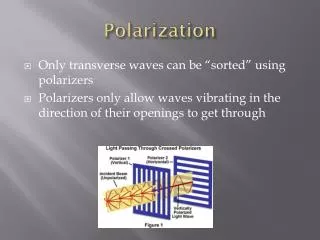
What is Polarized Light? • Light is oscillating electric and magnetic fields • Polarization is labeled by the shape of the trace of the tip of the E vector • Each polarization has an orthogonal state • Incoherent light can contain many polarization states Stokes Parameters describe partially polarized light I = RR + LL Q = RL + LR U = i(LR – RL) V = LL - RR For circular feeds Alternate representation: • pol. angle (EVPA)f = 0.5 atan (U/Q) • polarized intensity p = sqrt(Q2 + U2) • fractional linear m = p / I • fractional circular v = |V | / I Greg Taylor, Synthesis Imaging School, 18 June 2002
3C 31 VLA @ 8.4 GHz E-Vectors Laing (1996) 3 kpc Greg Taylor, Synthesis Imaging School, 18 June 2002
Perley & Carilli (1996) Cygnus A B-Vectors VLA @ 8.5 GHz 10 kpc Greg Taylor, Synthesis Imaging School, 18 June 2002
1055+018 Attridge et al 1999 VLBA @ 5 GHz Greg Taylor, Synthesis Imaging School, 18 June 2002
R Aquirrii Stellar SiO Masers Boboltz et al 1998 VLBA @ 43 GHz Greg Taylor, Synthesis Imaging School, 18 June 2002
Taylor (1998) 15 12 8 GHz Greg Taylor, Synthesis Imaging School, 18 June 2002
See Review of “Cluster Magnetic Fields” by Carilli & Taylor 2002 (ARA&A) Greg Taylor, Synthesis Imaging School, 18 June 2002
Parallactic Angle Greg Taylor, Synthesis Imaging School, 18 June 2002
Bad D-term solution Good D-term solution Greg Taylor, Synthesis Imaging School, 18 June 2002
Compact Symmetric Objects (CSOs) VLBA @ 8.4 GHz Peck & Taylor (2001) Greg Taylor, Synthesis Imaging School, 18 June 2002
Practical VLBI polarization angle calibration Greg Taylor, Synthesis Imaging School, 18 June 2002
1) Find a Calibrator Greg Taylor, Synthesis Imaging School, 18 June 2002
2) Estimate f_VLA Greg Taylor, Synthesis Imaging School, 18 June 2002
2200+420 3) Sum Q and U over VLBA image. 4) Compute f_VLBA = 0.5 atan (U/Q) 5) Rotate VLBA data by (f_VLA – f_VLBA) Greg Taylor, Synthesis Imaging School, 18 June 2002
Greg Taylor, Synthesis Imaging School, 18 June 2002