Download
1 / 73
810 likes | 1.02k Views
Chapter 1: Routing Services. CCNP ROUTE: Implementing IP Routing. Chapter 1 Objectives. Describe common enterprise traffic requirements and network design models. Describe how to create a plan for implementing routing services in an enterprise network.

E N D
Chapter 1: Routing Services CCNP ROUTE: Implementing IP Routing
Chapter 1 Objectives • Describe common enterprise traffic requirements and network design models. • Describe how to create a plan for implementing routing services in an enterprise network. • Review the fundamentals of routing and compare various routing protocols.
Complex Enterprise Network Frameworks, Architectures, and Models
Traffic Conditions in a Converged Network • Modern networks must support various types of traffic: • Voice and video traffic • Voice applications traffic • Mission-critical traffic • Transactional traffic • Network management traffic • Routing protocol traffic • This mix of traffic greatly impacts the network requirements such as security and performance. • To help enterprises, Cisco has developed the Intelligent Information Network (IIN).
Cisco Intelligent Information Network • The Intelligent Information Network (IIN): • Integrates networked resources and information assets. • Extends intelligence across multiple products and infrastructure layers. • Actively participates in the delivery of services and applications. • The IIN technology vision consists of 3 three phases in which functionality can be added to the infrastructure as required: • Integrated transport • Integrated services • Integrated applications
3 Phases of the IIN • Phase 1: Integrated transport • Integrates data, voice, and video transport into a single, standards-based, modular network simplifying network management and generating enterprise-wide efficiencies. • Phase 2: Integrated services • Integrated services help to unify common elements, such as storage and data center server capacity. • IT resources can now be pooled and shared, or virtualized, to address the changing needs of the organization. • Business continuity is also enhanced in the event of a local systems failure because shared resources across the IIN can provide needed services. • Phase 3: Integrated applications • This phase focuses on making the network application-aware so that it can optimize application performance and more efficiently deliver networked applications to users.
Cisco SONA Framework • The Cisco Service-Oriented Network Architecture (SONA) is an architectural framework to create a dynamic, flexible architecture and provide operational efficiency through standardization and virtualization. • SONA provides guidance, best practices, and blueprints for connecting network services and applications to enable business solutions. • In this framework, the network is the common element that connects and enables all components of the IT infrastructure. • SONA help enterprises achieve their goals by leveraging: • The extensive Cisco product-line services • The proven Cisco architectures • The experience of Cisco and its partners
Cisco SONA Framework Layers The SONA framework outlines three layers: Application Layer: Interactive Services Layer: Network Infrastructure Layer:
SONA: Network Infrastructure Layer • This layer provides connectivity anywhere and anytime. • All the IT resources (servers, storage, and clients) are interconnected across a converged network foundation. • This layer represents how these resources exist in different places in the network (campus, branch, data center, WAN, MAN and with the teleworker).
SONA: Interactive Services Layer • Enables efficient allocation of resources to applications and business processes delivered through the networked infrastructure. • Application and business processes include: • Voice and collaboration services • Mobility services • Security and identity services • Storage services • Computer services • Application networking services • Network infrastructure virtualization • Services management • Adaptive management services
SONA: Application Layer • This layer’s objective is to meet business requirements and achieve efficiencies by leveraging the interactive services layer. • Includes business applications and collaboration applications such as: • Commercial applications • Internally developed applications • Software as a Services (SaaS) • Composite Apps/SOA
Updated SONA Framework Cisco Systems has recently updated the SONA framework: Cisco designs, tests, and validates sets of modular, connected infrastructure elements organized by places in the network (PINs).
Cisco Enterprise Architecture The places in the network in the SONA Network Infrastructure Layer have been identified as follows:
Campus Architecture Provides: • High availability with a resilient multilayer design and redundant hardware and software features. • Automatic procedures for reconfiguring network paths when failures occur. • Multicast to provide optimized bandwidth consumption. • Quality of Service (QoS). • Integrated security. • Flexibility to add IP security (IPsec) and MPLS VPNs, identity and access management, and VLANs to compartmentalize access.
Branch Architecture • Provides head-office applications and services, such as security, Cisco IP Communications, and advanced application performance. • Integrates security, switching, network analysis, caching, and converged voice and video services into a series of integrated services routers in the branch. • Enterprises can centrally configure, monitor, and manage devices that are located at remote sites.
Data Center Architecture • Adaptive network architecture that supports the requirements for consolidation, business continuance, and security. • Redundant data centers provide backup services using synchronous and asynchronous data and application replication. • The network and devices offer server and application load balancing to maximize performance. • This solution allows the enterprise to scale without major changes to the infrastructure.
Teleworker Architecture • Also called the Enterprise Branch-of-One, it allows enterprises to deliver secure voice and data services to remote SOHO offices over a broadband access service. • Centralized management minimizes the IT support costs. • Campus security policies are implemented using robust integrated security and identity-based networking services. • Staff can securely log on to the network over an always-on VPN and gain access to authorized applications and services.
Cisco Hierarchical Network Model • The three-layer hierarchical model is used extensively in network design. • The hierarchical model consists of the: • Access layer • Distribution layer • Core layer • It provides a modular framework that allows design flexibility and facilitates implementation and troubleshooting. • The hierarchical model is useful for smaller networks, but does not scale well to today’s larger, more complex networks.
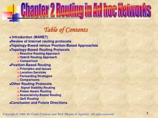
Enterprise Composite Network Model • The Enterprise Composite Network Model divides the network into three functional areas: Service Provider Edge Enterprise Edge Enterprise Campus
Enterprise Composite Network Model Service Provider Edge Enterprise Edge Enterprise Campus Building Access E-Commerce ISP A Building Distribution Corporate Internet ISP B Edge Distribution Core (Campus backbone) Management Remote Access VPN PSTN Server Farm WAN Frame Relay / ATM
Modules in the Enterprise Campus Service Provider Edge Enterprise Edge Enterprise Campus Building Access E-Commerce ISP A Building Distribution Corporate Internet ISP B Edge Distribution Core (Campus backbone) Management Remote Access VPN PSTN Server Farm WAN Frame Relay / ATM
Modules in the Enterprise Edge Service Provider Edge Enterprise Edge Enterprise Campus Building Access E-Commerce ISP A Building Distribution Corporate Internet ISP B Edge Distribution Core (Campus backbone) Management Remote Access VPN PSTN Server Farm WAN Frame Relay / ATM
Modules in the Service Provider Edge Service Provider Edge Enterprise Edge Enterprise Campus Building Access E-Commerce ISP A Building Distribution Corporate Internet ISP B Edge Distribution Core (Campus backbone) Management Remote Access VPN PSTN Server Farm WAN Frame Relay / ATM
Creating an Implementation Plan • An effective, documented implementation plan is a result of good processes and procedures during network design, implementation, and performance testing. • There are two approaches to implementing changes to a network. • Ad-hoc approach • Structured approach
Ad-hoc Approach • The many tasks such as deploying new equipment, connectivity, addressing, routing, and security are implemented and configured as required without planning any of the tasks. • With such an approach, it is more likely that scalability issues, suboptimal routing, and security issues can occur. • A good implementation plan is required to avoid such difficulties.
Structured Approach • Prior to implementing a change many considerations are taken into account. • The design and implementation plan are completed, and may include a new topology, an IP addressing plan, a solution to scalability issues, a link utilization upgrade, remote network connectivity, and changes to other network parameters. • The design and implementation plan must meet both technical and business requirements. • All details are documented in the implementation plan prior to the implementation. • After successful implementation, the documentation is updated to include the tools and resources used, and the implementation results.
Models and Methodologies • There are there are many models and methodologies used in IT that define a lifecycle approach using various processes to help provide high quality IT services. • No need to reinvent the wheel. • Examples of these models: • The Cisco Lifecycle Services (PPDIOO) model • IT Infrastructure Library (ITIL) • The Fault, Configuration, Accounting, Performance, and Security (FCAPS) model • International Organization for Standardization (ISO) • The Telecommunications Management Network (TMN) model • Telecommunications Standardization Sector (ITU-T)
Cisco Lifecycle Services (PPDIOO) Model The Cisco Lifecycle Services approach defines six phases in the network lifecycle and is referred to as the PPDIOO model: Design Optimize Prepare Implement Plan Operate
PPDIOO – Prepare, Plan, and Design • The PPDIOO methodology begins with these three basic steps: • Step 1: Identify customer requirements • Step 2: Characterize the existing network and sites • Step 3: Design the network topology and solutions • Once the design is defined, the implementation plan can be executed. Design Plan Prepare Design the network Identify customer requirements Characterize existing network
PPDIOO – Implement, Operate, Optimize • The next three steps include: • Step 4: Plan the implementation: • Step 5: Implement and verify the design: • Step 6: Monitor and optionally redesign: Operate / Optimize Design Implement Monitor / Redesign Plan the implementation Implement and Verify
Implementation Plan documentation • The implementation plan documentation should include the following: • Network information • Tools required • Resources required • Implementation plan tasks • Verification tasks • Performance measurement and results • Screen shots and photos, as appropriate • The documentation creation process is not finished until the end of the project, when the verification information is added to it.
Sample Implementation Plan • Project contact list and statements of work, to define all of the people involved and their commitments to the project • Site and equipment location information and details of how access to the premises is obtained • Tools and resources required • Assumptions made • Tasks to be performed, including detailed descriptions • Network staging plan
Routing • This section addresses the ways in which routers learn about networks and how routers can incorporate static and dynamic routes. • A router can be made aware of remote networks in two ways: • An administrator can manually configure the information (static routing) • The router can learn from other routers (dynamic routing). • A routing table can contain both static and dynamically recognized routes.
Static Routes • A static route can be used in the following circumstances: • To have absolute control of routes used by the router. • When a backup to a dynamically recognized route is necessary. • When it is undesirable to have dynamic routing updates forwarded across slow bandwidth links. • To reach a stub network.
Static Routing • Configure a static route with the ip route command. Router(config)# ip route prefix mask address interface dhcp distance name next-hop-name permanenttrack number tag tag
Configuring a Default Static Route • R2 is configured with a static route to the R1 LAN and a default static route to the Internet. • R1 is configured with a default static route. R2(config)# ip route 172.16.1.0 255.255.255.0 S0/0/0 R2(config)# ip route 0.0.0.0 0.0.0.0 192.168.1.1 S0/0/0 S0/0/1 S0/0/0 Internet R1 192.168.1.1 R2 10.1.1.2 192.168.1.2 10.1.1.1 Fa0/0 Fa0/0 172.16.1.0 /24 10.2.0.0 /16 R1(config)# ip route 0.0.0.0 0.0.0.0 10.1.1.1 R1(config)# exit R1# show ip route <output omitted> Gateway of last resort is not set C 172.16.1.0 is directly connected, FastEthernet0/0 C 10.1.1.0 is directly connected, Serial0/0/0 S* 0.0.0.0/0 [1/0] via 10.1.1.1 R1#
Dynamic Routing • Dynamic routing (RIPv1, RIPv2, EIGRP, OSPF, and IS-IS) allows the network to adjust to changes in the topology automatically, without administrator involvement. • The information exchanged by routers includes the metric or cost to each destination (this value is sometimes called the distance). • Different routing protocols base their metric on different measurements, including hop count, interface speed, or more-complex metrics.
On-Demand Routing • Static routes must be manually configured and updated when the network topology changes. • Dynamic routing protocols use network bandwidth and router resources. • Resource usage of dynamic routing can be considerable. • A third option is to use the Cisco On-Demand Routing (ODR) feature. • ODR uses minimal overhead compared to a dynamic routing protocol and requires less manual configuration than static routes.
ODR • ODR is applicable in a hub-and-spoke topology only. • ODR works with the Cisco Discovery Protocol (CDP) to carry network information between spokes and hub router. • The hub router sends a default route to the spokes that points back to itself and installs the stub networks reported by ODR in its routing table. • The hub router can then be configured to redistribute the ODR learned routes into a dynamic routing protocol.
Configuring ODR • ODR is configured: • On all routers, CDP must be enabled. • On the hub router using therouter odrglobal config command. • On the stub routers, no IP routing protocol can be configured. • ODR learned routes appear in the hub router routing table with an entry of “o” and an administrative distance of 160. • On each spoke router, the routing table contains only its connected networks and a static default route injected by ODR from the hub.