Download
1 / 95
970 likes | 1.21k Views
Chapter 4 Network Layer. Chapter 4: Network Layer. Chapter goals: understand principles behind network layer services: network layer service models forwarding versus routing how a router works routing (path selection) dealing with scale IPv4 and IPv6. 4. 1 Introduction

E N D
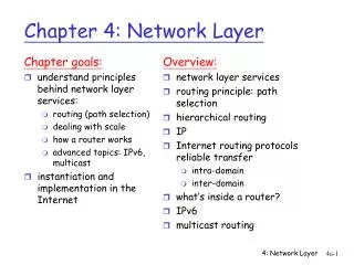
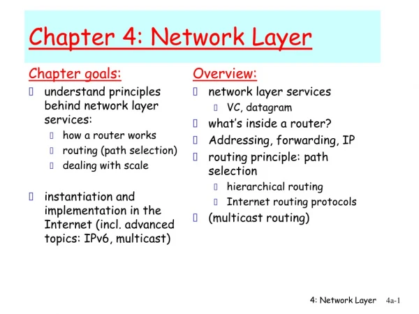
Chapter 4: Network Layer Chapter goals: • understand principles behind network layer services: • network layer service models • forwarding versus routing • how a router works • routing (path selection) • dealing with scale • IPv4 and IPv6
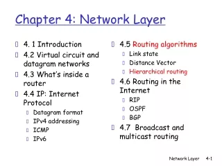
4. 1 Introduction 4.2 Virtual circuit and datagram networks 4.3 What’s inside a router 4.4 IP: Internet Protocol Datagram format IPv4 addressing ICMP IPv6 4.5 Routing algorithms Link state Distance Vector Hierarchical routing 4.6 Routing in the Internet RIP OSPF BGP Chapter 4: Network Layer
transport segment from sending to receiving host on sending side encapsulates segments into datagrams on rcving side, delivers segments to transport layer network layer protocols in every host and router router examines header fields in all IP datagrams passing through it network data link physical network data link physical network data link physical network data link physical network data link physical network data link physical network data link physical network data link physical network data link physical network data link physical network data link physical application transport network data link physical application transport network data link physical Network layer
Two Key Network-Layer Functions • forwarding: move packets from router’s input to appropriate router output • routing: determine route taken by packets from source to dest. • routing algorithms analogy: • routing: process of planning trip from source to dest • forwarding: process of getting through single interchange
routing algorithm local forwarding table header value output link 0100 0101 0111 1001 3 2 2 1 value in arriving packet’s header 1 0111 2 3 Interplay between routing and forwarding
Example services for individual datagrams: guaranteed delivery guaranteed delivery with less than 40 msec delay Example services for a flow of datagrams: in-order datagram delivery guaranteed minimum bandwidth to flow restrictions on changes in inter-packet spacing (jitter) Network service model Q: What service model for “channel” transporting datagrams from sender to receiver?
4 3 2 1 To hand set 5 4 3 2 1 To hand set To hand set 7 6 5 6 4 5 3 4 3 2 Why jitter is important, E.g., VoIP VoIP requires that voice samples be played at a constant rate • Moderate delay is not a problem 5 6 7
4 3 2 1 5 To hand set 5 4 3 2 1 6 To hand set 6 5 4 3 2 To hand set 6 5 4 3 To hand set 6 5 4 7 To hand set 6 5 To hand set 6 To hand set 7 Why jitter is important, E.g., VoIP VoIP requires that voice samples be played at a constant rate • This buffer size just barely worked. • If the delay had been bigger, then the voice would have dropped out, unless a larger buffer was used. • Note that the problem was not the delay was large, but the change in delay
4 3 2 1 To hand set 5 4 3 2 1 Why jitter is important, E.g., VoIP VoIP requires that voice samples be played at a constant rate 5 6 8 7 9 To hand set 9 8 7 6 5 4 3 2 • Jitter can cause the buffer to fill or empty. • In general, the larger the jitter, the larger the required buffer. • A large buffer adds delay so that the buffer delay is the same as the worst-case delay • If average delay is small, but jitter is large, then a large buffer is needed, resulting in long delay
Network layer service models: Guarantees ? Network Architecture Internet ATM ATM ATM ATM Service Model best effort CBR VBR ABR UBR Congestion feedback no (inferred via loss) no congestion no congestion yes no Bandwidth none constant rate guaranteed rate guaranteed minimum none Loss no yes yes no no Order no yes yes yes yes Timing no yes yes no no CBR = constant bit-rate (phone, not VoIP) VBR = variable bit-rate (e.g., variable bit-rate video, audio) ABR = available bit-rate. Like best effort but with guaranteed minimum bit-rate, but it gets feedback from the network to adjust the sending rate UBR = unspecified bit-rate. Like best effort
Why the different service models • Some application require bit-rate and delay guarantees. • E.g., VoIP needs low delay (under 150 ms one-way is best, over 400ms one-way is typically unacceptable) and 15kbps • Thus, it would be nice if whenever the VoIP started, the network would reserve enough bandwidth for the call • otherwise, I will just use my landline • i.e., I am willing to pay for this service (except that paying for calls this against network neutrality) • But this is wasteful • In VoIP, only one side talks at a time • But the network can’t reserve half of the bit-rate. • The network can reserve the full bandwidth. And give the unused bandwidth as ABR (with the average bandwidth of ½ the VoIP bit-rate, since this is the average unused bit-rate) • However, if the VoIP traffic requires the bandwidth, the ABR must stop.
4. 1 Introduction 4.2 Virtual circuit and datagram networks 4.3 What’s inside a router 4.4 IP: Internet Protocol Datagram format IPv4 addressing ICMP IPv6 4.5 Routing algorithms Link state Distance Vector Hierarchical routing 4.6 Routing in the Internet RIP OSPF BGP Chapter 4: Network Layer
Network layer connection and connection-less service • datagram network provides network-layer connectionless service • VC network provides network-layer connection service
call setup, teardown for each call before data can flow each packet carries VC identifier (not destination host address) every router on source-dest path maintains “state” for each passing connection link, router resources (bandwidth, buffers) may be allocated to VC (dedicated resources = predictable service) “source-to-dest path behaves much like telephone circuit” performance-wise network actions along source-to-dest path Virtual circuits
VC implementation a VC consists of: • path from source to destination • VC numbers • entries in forwarding tables in routers along path • A packet belonging to VC carries VC number (rather than dest address) • However, it is difficult to ensure that the VC number is unique across the network • Instead, the VC number is changed at each link
data data data data 1 1 1 1 Packet Switching • Data is in packets, not streams. • Must be digital • Each packet has an address • A switch/router reads the whole packet, then reads the address and forwards the packet – store and forward If destination is 1, then next hop is C If destination is 1, then next hop is B If destination is 1, then next hop is B A C D client Server: address = 1 F E
VC number 22 32 12 3 1 2 interface number Incoming interface Incoming VC # Outgoing interface Outgoing VC # 1 12 3 22 2 63 1 18 3 7 2 17 1 97 3 87 … … … … Forwarding table Forwarding table in northwest router: Routers maintain connection state information! It is much easier to perform table lookup (to get the next hop information) on a 20-bit VC number than a 32 bit IP address (but this is not that important with high-speed ASICs)
used to setup, maintain teardown VC used in ATM, frame-relay, X.25 not used in today’s Internet application transport network data link physical application transport network data link physical Virtual circuits: signaling protocols 6. Receive data 5. Data flow begins 4. Call connected 3. Accept call 1. Initiate call 2. incoming call
no call setup at network layer routers: no state about end-to-end connections no network-level concept of “connection” packets forwarded using destination host address packets between same source-dest pair may take different paths application transport network data link physical application transport network data link physical Datagram networks 1. Send data 2. Receive data
MPLS (Multiprotocol Label Switching) • MPLS is widely used in large ISPs (e.g., AT&T) • MPLS is a compromise between IP and VC. • MPLS can run over an IP network. • Today, most routers support MPLS and IP at the same time • MPLS uses label switching, which the the same idea as VC number • Packets have a 20-bit label • When a packet arrives on an interface, the a table lookup is performed, the output interface is found, next label is found, and the current label is changed to the next label • Label lookup is faster than IP address lookup. But speed isn’t really a concern
MPLS Architecture • Conceptually, there are three types of routers • Ingress routers – where packets enter the network (e.g., move from UD to Cogent ) • Egress routers – where packets exit the network (e.g., move from Cogent to AT&T) • Internal routers – where packets remain inside the network • When an IP packet arrives at an ingress routers, a lookup is performed based on the IP address • If a match is found, then an MPLS header is put on the packet along with the next hop label. That is, the packet is placed into an MPLS tunnel • From this point, the IP header is never examined. The forwarding is based on the MPLS label • When the packet arrives at an internal router, the label is switched, just like in a VC • When the packet reaches the egress router, the MPLS header is removed and the IP address is examined to determine the next hop (just like a regular IP router)
MPLS and Traffic Engineering • MPLS allows packets to follow tunnels • These tunnels can be designed to reduce the offered load on a link Chicago NY This link is congested with NY-SF, DC-SF, and Chicago-SF traffic SF Saint Louis DC Dallas
MPLS and Traffic Engineering Chicago NY SF Saint Louis DC Dallas • Packets arrive at Saint Louis with SF as destination, but they take different paths. • MPLS can do this • But IP forwarding cannot do this • IP forwarding only examines the destination IP • Examining the 64 bit source and destination could accomplish this, but that would take a large table
4. 1 Introduction 4.2 Virtual circuit and datagram networks 4.3 What’s inside a router 4.4 IP: Internet Protocol Datagram format IPv4 addressing ICMP IPv6 4.5 Routing algorithms Link state Distance Vector Hierarchical routing 4.6 Routing in the Internet RIP OSPF BGP Chapter 4: Network Layer
Router Architecture Overview Two key router functions: • run routing algorithms/protocol (RIP, OSPF, BGP) • forwarding datagrams from incoming to outgoing link
Input Port Functions Decentralized switching: • given datagram dest., lookup output port using forwarding table in input port memory • goal: complete input port processing at ‘line speed’ • queuing: if datagrams arrive faster than forwarding rate into switch fabric Physical layer: bit-level reception Data link layer: e.g., Ethernet see chapter 5
Memory Input Port Output Port System Bus Switching Via Memory First generation routers: • traditional computers with switching under direct control of CPU • packet copied to system’s memory • speed limited by memory bandwidth (2 bus crossings per datagram)
Switching Via a Bus • datagram from input port memory to output port memory via a shared bus • bus contention: switching speed limited by bus bandwidth • 32 Gbps bus, Cisco 5600: sufficient speed for access and enterprise routers
Switching Via An Interconnection Network • overcome bus bandwidth limitations • Banyan networks, other interconnection nets initially developed to connect processors in multiprocessor • advanced design: fragmenting datagram into fixed length cells, switch cells through the fabric. • Cisco 12000: switches 60 Gbps through the interconnection network
Output Ports • Buffering required when datagrams arrive from fabric faster than the transmission rate • Scheduling discipline chooses among queued datagrams for transmission
Output port queueing • buffering when arrival rate via switch exceeds output line speed • queueing (delay) and loss due to output port buffer overflow!
. RTT C N How much buffering? • RFC 3439 rule of thumb: average buffering equal to “typical” RTT (say 250 msec) times link capacity C • e.g., C = 10 Gps link: 2.5 Gbit buffer • Recent recommendation: with N flows, buffering equal to
Input Port Queuing • Fabric slower than input ports combined -> queueing may occur at input queues • Head-of-the-Line (HOL) blocking: queued datagram at front of queue prevents others in queue from moving forward • queueing delay and loss due to input buffer overflow!
4. 1 Introduction 4.2 Virtual circuit and datagram networks 4.3 What’s inside a router 4.4 IP: Internet Protocol Datagram format IPv4 addressing ICMP IPv6 4.5 Routing algorithms Link state Distance Vector Hierarchical routing 4.6 Routing in the Internet RIP OSPF BGP Chapter 4: Network Layer
Host, router network layer functions: • ICMP protocol • error reporting • router “signaling” • IP protocol • addressing conventions • datagram format • packet handling conventions • Routing protocols • path selection • RIP, OSPF, BGP forwarding table The Internet Network layer Transport layer: TCP, UDP Network layer Link layer physical layer
4. 1 Introduction 4.2 Virtual circuit and datagram networks 4.3 What’s inside a router 4.4 IP: Internet Protocol Datagram format IPv4 addressing ICMP IPv6 4.5 Routing algorithms Link state Distance Vector Hierarchical routing 4.6 Routing in the Internet RIP OSPF BGP Chapter 4: Network Layer
IP protocol version number header length (bytes) for fragmentation/ reassembly “type” of data max number remaining hops (decremented at each router) IPv4 datagram format 32 bits total datagram length (bytes) type of service head. len ver length fragment offset flgs 16-bit identifier upper layer time to live header checksum 32 bit source IP address 32 bit destination IP address upper layer protocol to deliver payload to E.g. timestamp, record route taken, specify list of routers to visit. Typically, these are ignored Options (if any) how much overhead with TCP? • 20 bytes of TCP • 20 bytes of IP • = 40 bytes + app layer overhead data (variable length, typically a TCP or UDP segment)
network links have MTU (max.transfer size) - largest possible link-level frame. different link types, different MTUs E.g., ethernet allows 1500B frames 802.11 allows 2346B frames It would be very difficult for the end host to know the correct packet size Note that larger packets are more efficient (less bandwidth is consumed by the header) Large IP datagram divided (“fragmented”) within the network one datagram becomes several datagrams “reassembled” only at final destination IP header bits used to identify, order related fragments IPv4 Fragmentation & Reassembly fragmentation: in: one large datagram out: 3 smaller datagrams reassembly
length =1500 length =1500 length =4000 length =1040 ID =x ID =x ID =x ID =x fragflag =0 fragflag =1 fragflag =1 fragflag =0 offset =0 offset =0 offset =370 offset =185 One large datagram becomes several smaller datagrams IPv4 Fragmentation and Reassembly Example • 4000 byte datagram • MTU = 1500 bytes 1480 bytes in data field offset = 1480/8
Stealthy Scanning • Before attacking a network, one must learn which hosts are present. • That is, which IP addresses have host that are running various services (e.g., listening on various TCP ports) • This is done by scanning. For example, sending an ICMP ping message to random IP address or sending TCP-SYN messages • What happens if a host receives an TCP-SYN on a port that is not listening • It depends on the OS, but the typically, a TCP-RST packet is generated • ISPs (e.g., UD) will look for scanners and take action (e.g., disconnect them) • So what is an attacker to do?
Stealthy Scanning victim If victim exists and port is open: TCP-SYN-ACK Some machine is confused (it didn’t send a TCP-SYN) TCP-RST with IP-ID = X + 1 SomeMachine ICMP echo-request (ping) TCP-SYN: Dest=Victim, Source=SomeMachine attacker ICMP echo reply with IP-ID = X+2 ICMP echo reply with IP-ID = X Since the IP-ID incremented by 2, the victim must have sent a SYN-ACK. If the IP-ID only incremented by 1, then the victim is not listening on the port, or does not exist Attacker records IP-ID=X
4. 1 Introduction 4.2 Virtual circuit and datagram networks 4.3 What’s inside a router 4.4 IP: Internet Protocol Datagram format IPv4 addressing ICMP IPv6 4.5 Routing algorithms Link state Distance Vector Hierarchical routing 4.6 Routing in the Internet RIP OSPF BGP Chapter 4: Network Layer
IP address: 32-bit identifier for host, router interface interface: connection between host/router and physical link router’s typically have multiple interfaces host typically has a small number (ethernet and wifi) IP addresses associated with each interface It is possible to have more than one Virtual machines could each have an IP address 223.1.1.2 223.1.2.1 223.1.3.27 223.1.3.1 223.1.3.2 223.1.2.2 IP Addressing: introduction 223.1.1.1 223.1.2.9 223.1.1.4 223.1.1.3 223.1.1.1 = 11011111 00000001 00000001 00000001 223 1 1 1 Ipv4 special addresses: http://tools.ietf.org/html/rfc5735
IP address: subnet part (high order bits) host part (low order bits) What’s a subnet ? device interfaces with same subnet part of IP address can physically reach each other without intervening router (but perhaps a layer 2 switch) Subnets 223.1.1.1 223.1.2.1 223.1.1.2 223.1.2.9 223.1.1.4 223.1.2.2 223.1.1.3 223.1.3.27 subnet 223.1.3.2 223.1.3.1 network consisting of 3 subnets
Recipe To determine the subnets, detach each interface from its host or router, creating islands of isolated networks. Each isolated network is called a subnet. 223.1.1.0/24 223.1.2.0/24 223.1.3.0/24 Subnets Subnet mask: /24
How many? Subnets 223.1.1.2 223.1.1.1 223.1.1.4 223.1.1.3 223.1.7.0 223.1.9.2 223.1.9.1 223.1.7.1 223.1.8.1 223.1.8.0 223.1.2.6 223.1.3.27 223.1.2.1 223.1.2.2 223.1.3.1 223.1.3.2
IP addressing: CIDR CIDR:Classless InterDomain Routing • subnet portion of address of arbitrary length • address format: a.b.c.d/x, where x is # bits in subnet portion of address Subnet part or CIDR-block host part 11001000 0001011100010000 00000000 200.23.16.0/23
IP addresses: how to get one? Q: How does network get subnet part of IP addr? A: gets allocated portion of its provider ISP’s address space ISP's block 11001000 00010111 00010000 00000000 200.23.16.0/20 Organization 0 11001000 00010111 00010000 00000000 200.23.16.0/23 Organization 1 11001000 00010111 00010010 00000000 200.23.18.0/23 Organization 2 11001000 00010111 00010100 00000000 200.23.20.0/23 ... ….. …. …. Organization 7 11001000 00010111 00011110 00000000 200.23.30.0/23