Download
1 / 25
290 likes | 945 Views
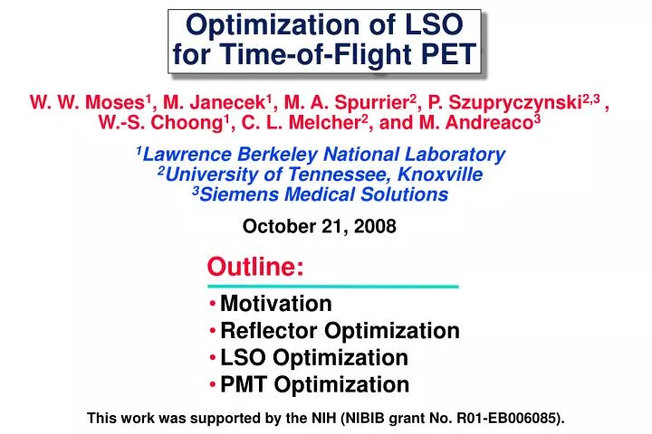
Motivation Reflector Optimization LSO Optimization PMT Optimization. Optimization of LSO for Time-of-Flight PET. W. W. Moses 1 , M. Janecek 1 , M. A. Spurrier 2 , P. Szupryczynski 2,3 , W.-S. Choong 1 , C. L. Melcher 2 , and M. Andreaco 3

E N D
Motivation Reflector Optimization LSO Optimization PMT Optimization Optimization of LSOfor Time-of-Flight PET W. W. Moses1, M. Janecek1, M. A. Spurrier2, P. Szupryczynski2,3 ,W.-S. Choong1, C. L. Melcher2, and M. Andreaco3 1Lawrence Berkeley National Laboratory2University of Tennessee, Knoxville3Siemens Medical Solutions October 21, 2008 Outline: This work was supported by the NIH (NIBIB grant No. R01-EB006085).
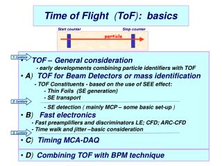
500 ps timing resolution 7.5 cm localization D Time-of-Flight in PET c = 30 cm/ns • Can localize source along line of flight. • Time of flight information reduces noise in images. • Variance reduction given by 2D/ct. • 500 ps timing resolution5x reduction in variance! • Time of Flight Provides a Huge Performance Increase! • Largest Improvement in Large Patients
Commercial TOF PET w/ LSO ~550 ps Coincidence Timing Achieved
Our Goal:“Demonstration” TOF PET Camera • With better timing resolution (t), huge gains predicted(23x variance reduction for 100 ps timing) • Measure image improvement vs. timing resolution • Use LSO scintillator • Don’t change other factors that influence SNR(efficiency, scatter fraction, etc.) Achieve the Best Timing Possible w/ LSO
What Limits Timing Resolution? Non-TOF Block Detector Module Baseline 160 ps Crystal Geometry 326 ps Light Sharing 454 ps PMT 422 ps PMT Array 274 ps • Many Factors • “Optical Geometry” Particularly Important
Timing Values will be for a Single Detector* Windowed Timing Photopeakevents LSO 1 cm3BaF2 TriggerDetector H5321 Ge-68 R9800 TestDetector CFD Start TAC Stop CFD Canberra 454 F=0.2, D=0.6 ns Canberra 454 F=0.2, D=0.6 ns Ortec 566 Timing ShapingAmplifier ADC Pulse Height NI-7833R +/- fwhm Photopeak events *Unless explicitly mentioned otherwise • Only Accept Events in Photopeak Window • Subtract (in Quadrature) 150 ps Trigger Contribution
Proposed Side-Coupled Design PMT 384 ps (543 ps coinc.) Conventional Geometry (End-Coupled Crystal) ScintillatorCrystal 218 ps Proposed Geometry(Side-Coupled Crystal) PMT Shorter Optical Path Length & Fewer Reflections
Hole in ReflectorOn Top Face of Crystals Two LSO Crystals (each 6.15 x 6.15 x 25 mm3) Detector Module Design Reflector (on all five faces of each crystal, including the face between the two crystals) PMT (HamamatsuR-9800) Optical Glue (between lower crystal faces and PMT) Two Side-Coupled Scintillator Crystals per PMT
Crystal ofInteraction Detector Ring Geometry • Top face of each crystal (with hole in reflector) is coupled via a small (<1 mm) air gap to the edge of one opposing PMT. • Light seen by the opposing PMT is used to decode the crystal of interaction. Exploded View Crystals Decoded by Opposing PMT
Camera Geometry Section of Detector Ring Lead Shielding Modules • Detector ring is 825 mm diameter, 6.15 mm axial • 192 detector modules, 384 LSO scintillator crystals • Adjustable gap (6 – 150 mm) between lead shields allows “scatter-free” and “3-D” shielding geometries “Real” Single-Ring PET Camera for Humans & Phantoms
Optimization: Surface Finish & Reflector Requirements • Best Possible Timing Resolution • Good Light Collection Efficiency • Good Energy Resolution • Manufacturable: • Easy • Reliable & Reproducible • Rugged • Well-Controlled Light from Top Surface • Starting Point: Saw Cut LSO w/ Teflon Tape Both Performance & Manufacturing Important
Surface & Reflector Optimization Method • 6.15 x 6.15 x 25 mm3 • Reflector on 5 Sides • Optical Grease • No Hole on Top • Measure Timing of “Raw” Crystal(saw cut finish, Teflon tape reflector) • Apply Surface Treatment • Apply Reflector • Re-Measure Timing • Compute Percent Change • Repeat for 5 Crystals & Average Results • Do for All Surface / Reflector Combinations(>100 crystals, each measured twice) R-9800 Same PMT forall measurements Measure PercentageChange in Timing
Average 1.00 1.02 1.01 0.99 1.00 1.00 0.98 Average 1.01 0.96 1.03 Surface & Reflector Results Reflector Saw Cut Chemically Mechanically Etched Polished Air Gap Teflon 1.00 ± 0.17 0.94 ± 0.10 1.06 ± 0.09 ESR 1.01 ± 0.08 0.96 ± 0.16 1.08 ± 0.08 Lumirror 1.03 ± 0.13 0.96 ± 0.06 1.04 ± 0.12 Glued ESR 0.99 ± 0.09 0.98 ± 0.03 1.01 ± 0.18 Lumirror 1.04 ± 0.10 0.97 ± 0.10 0.98 ± 0.22 Melinex 1.01 ± 0.16 0.99 ± 0.06 1.01 ± 0.20 Epoxy 1.00 ± 0.16 0.95 ± 0.09 1.00 ± 0.15 Paint 0.96 ± 0.03
Finished Crystal Etched Surface, White Primer Spray Paint
Pulse Height Performance Well-Coupled PMT Poorly-Coupled PMT 18% fwhm Good Energy Resolution & Crystal Decoding
Optimization: LSO Composition I0 I(t) = I0 exp(-t/) Light Output = I0 • Both Scintillators Have Same Light Output (photons/MeV) • Red Decay Time is 2x Longer Than Blue Decay Time • Predicted Timing Resolution 1/sqrt(I0) • Want High Total Light Output & Short Decay Time • Possible By Co-Doping LSO With Calcium
High Light Out The Good Stuff! Short 0.1% 0.3% 0.4% 0.2% = Ca-doped Optimization: LSO Composition Normal LSO Ca-Doping Gives High Light Output & Short
LSO Composition Optimization Method • 5 x 5 x 5 mm3 • Saw Cut Surface • Teflon on 5 Sides • Optical Grease • Get Samples of Normal & Co-Doped LSO • Measure Decay Time • Measure Relative Light Output • Compute Initial Intensity I0 • Measure Timing Resolution • Plot Timing Resolution vs. I0 R-9800 Same PMT forall measurements Measure Time Resolution vs. Initial Intensity
0.1% 0.4% 0.3% 0.2% = Ca-doped Measured Results: LSO Composition Normal LSO Scaled by1/sqrt(I0) • Ca-Doping Gives Good Timing Resolution • ~15% Improvement Over Normal LSO
Blue Sensitivity Index Peak QE Optimization: Photomultiplier Tube • Predicted Timing Resolution 1/sqrt(QE) • Want High Quantum Efficiency Version of PMT
PMT Optimization Method • 6.15 x 6.15 x 25 mm3 • Chemically etched • Lumirror reflector • Optical Grease • Same Crystal forall measurements • Couple “Standard” LSO Crystal to PMT(“normal” LSO, etched surface finish,Lumirror reflector glued to five sides) • Measure Timing • Repeat for all PMTs • Measure twice for each PMT R-9800 Measure Time Resolution vs. Blue Sensitivity
= “32% QE” PMTs Measured Results: High QE PMTs Normal (“28% QE”) PMTs Scaled by1/sqrt(Blue Index) • Increased QE Improves Timing Resolution by 7% • Expect 10% Improvement with 35% SBA PMT
FPGA CERNTDC Out… CFD 4 ADCs Sum Shaper CFD 4 ADCs Sum Shaper Electronics Based on Siemens “Cardinal” electronics. CFD triggers if any of 4 adjacent modules fire. CERN HPTDC digitizes arrival time w/ 24 ps LSB. Pulse height from all 8 modules read out on every trigger. FPGA uses pulse heights to identify interaction crystal. FPGA also does calibration, event formatting, etc. • Intrinsic Timing Resolution is 63 ps fwhm • With Detectors, Same Timing as NIM Electronics
Summary Hardware Single Coinc. TOF(ps fwhm) (ps fwhm) Gain End-Coupled Crystal 384 544 4.3 Side-Coupled Crystal 218 309 7.6 Etched, Reflector Paint 227 321 7.3 Co-Doped LSO 182 258 9.1 32% QE PMT 155 219 10.6 35% QE “SBA” PMT 148 209 11.1 • TOF PET with Significantly Better Timing is Possible • To Achieve, We Must “Think Outside the Block Detector”
Scintillator Array Thinned SiPM Array Future TOF PET Design? • Depth of Interaction & 150 ps Timing Resolution • 11x Reduction in Variance in Practical Geometry