Download

1 / 24
280 likes | 559 Views
Lab 2 EGR 262 – Fundamental Circuits Lab. EGR 262 Fundamental Circuits Lab Presentation for Lab # 1: Introduction to the Arduino UNO. Lab 2 EGR 262 – Fundamental Circuits Lab. 2. Arduino – Historical background

E N D
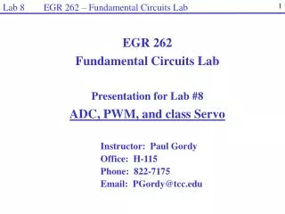
Lab 2 EGR 262 – Fundamental Circuits Lab EGR 262 Fundamental Circuits Lab Presentation for Lab #1: Introduction to the Arduino UNO
Lab 2 EGR 262 – Fundamental Circuits Lab 2 Arduino – Historical background “Arduino started in 2005 as a project for students at the Interaction Design Institute Ivrea in Ivrea, Italy. Arduino is a single-board microcontroller, intended to make the application of interactive objects or environments more accessible. The hardware consists of an open-source hardware board designed around an 8-bit Atmel AVR microcontroller, or a 32-bit Atmel ARM. Pre-programmed into the on-board microcontroller chip is a boot loader that allows uploading programs into the microcontroller memory without needing a chip (device) programmer. Arduino boards can be purchased pre-assembled or as do-it-yourself kits. Hardware design information is available for those who would like to assemble an Arduino by hand. It was estimated in mid-2011 that over 300,000 official Arduinos had been commercially produced.” (reference: http://en.wikipedia.org/wiki/Arduino)
Lab 2 EGR 262 – Fundamental Circuits Lab 3 Arduino Microcontroller Boards (www.arduino.cc) Arduino produces several versions of microcontrollers, including: Used in EGR 120 and EGR 262
Lab 2 EGR 262 – Fundamental Circuits Lab 4 Arduino Microcontrollers - specifications Each microcontroller has different specifications. A few specifications for three of the Arduino microcontrollers are listed below. • Arduino Mega 2560 R3 • Atmega 2560 8-bit AMTEL AVR RISC microprocessor • 54 digital I/O pins • 14 PWM digital I/O pins • 16 analog I/O pins • 16 MHz clock speed • 256 kB flash memory for storage of code • $55.56 • Arduino UNO R3 • Atmega 328 8-bit AMTEL AVR RISC microprocessor • 14 digital I/O pins • 6 PWM digital I/O pins • 6 analog I/O pins • 16 MHz clock speed • 32 kB flash memory for storage of code • $28.49 • Arduino DUE • AT91SAM3X8E 32- bit ARM Cortex-M3 microprocessor • 54 digital I/O pins • 12 PWM digital I/O pins • 12 analog I/O pins • 84 MHz clock speed • 512 kB flash memory for storage of code • $55.56
Lab 2 EGR 262 – Fundamental Circuits Lab • References: (many more available) • 1) Arduino web site (software, microcontrollers, tutorials, examples, etc) - www.arduino.cc/ • 2) Arduino Tutorials - http://www.ladyada.net/learn/arduino/ • Engadget (gadgets built using Arduinos) - http://www.engadget.com/tag/Arduino/ • 4) Instructables (gadgets using Arduinos) - http://www.instructables.com/id/Arduino-Projects/ • EGR 120 Arduino-BOT Lectures #1-5 - http://faculty.tcc.edu/PGordy/Egr120/ • TCC Library – Free Safari eBooks – You can access eBooks as follows: • Go to TCC’s home page and select Library • Select Library Catalog – eBooks • Select Safari Tech Books • Log in (usual ID and password) • Search for Arduino – Here are a few that I found:
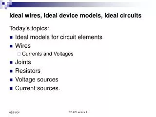
Lab 2 EGR 262 – Fundamental Circuits Lab 6 Powering the Arduino UNOThe Arduino can be powered using: USB cable (5V input) – OK for downloading and testing programs, but not for driving external circuits. Provides a weak 5V to the Arduino board AC to DC Adaptor (recommended 9 to 12V DC, 250mA or more, 2.1mm plug, centre pin positive) DC Power Supply (7V – 12V recommended, 6V – 20V limits) 4 AA Batteries ( ≈ 6V input) - Provides a weak 5V to the Arduino board 5 AA Batteries (≈ 7.5V input) Note: If both the USB and another source (AC/DC adapter, batteries, etc) are connected, the Arduino will select the stronger source. Typical Arduino UNO voltages:
Lab 2 EGR 262 – Fundamental Circuits Lab 7 Powering the Arduino-BOTWe will typically power the Arduino with an AC/DC adaptor. You can leave both the USB and the AC/DC adaptor connected and the Arduino will use the higher adaptor voltage. We will make 5V and GND (ground) connections to the breadboard as shown below. USB AC/DC Adaptor Plug
Lab 2 EGR 262 – Fundamental Circuits Lab 8 6 of the 14 are also PWM (8-bit Pulse Width Modulation) pins: ~11, ~10, ~9, ~6, ~5, ~3 AREF (Analog reference) – used to set the max analog input value Arduino UNO Hardware Specifications 14 Digital I/O Pins (D0-D13) LED connected to D13 for testing Header (for 22 gauge wire) Reset button ICSP header for communication with peripheral devices USB 16 MHz crystal oscillator Voltage regulator ATMega328 microprocessor DC Input (7V – 12V) Reset – LOW voltage resets the microcontroller (same as pressing the reset button) 3.3V, 5V, GND (ground) and Vin (unregulated input, such as 12V from an AC/DC Adaptor 6 Analog I/O Pins (A0-A5)
Lab 2 EGR 262 – Fundamental Circuits Lab 9 Arduino UNO Schematic (2 equivalent versions)
Lab 2 EGR 262 – Fundamental Circuits Lab 10 • The Arduino Programming Environment • The Arduino software (Arduino 1.05 or later) is available on lab computers and can also be downloaded from http://arduino.cc • The software requires no installation and can even be launched from a flash drive. • Open using the shortcut on the desktop or double-click Arduino • in the Arduino-1.0.5 folder as indicated below • The file opened is referred to as a “sketch” and will be automatically named using the date. You can rename it if you wish. The file below is named sketch_jan20a.ino
Lab 2 EGR 262 – Fundamental Circuits Lab 11 • Notes: • Verify is used to compile your program (or sketch). (It checks for errors). • Upload is used to send the program (sketch) to the Arduino via the USB cable. • Arduino programs have two main parts: • setup – a function to initialize items or to perform operations one time. • loop – a function with commands that will be repeated indefinitely • Serial.begin(baud rate) is used to establish serial communications between the Arduino and the computer. Data is transmitted at 9600 baud (bits/second). Note that Serial uses digital pins 0 and 1 so they cannot be used for other inputs/outputs. • Serial.print(text, values, or variables) is display information from the Arduino-BOT on the display window. • Select Serial Monitor to open a window to view printed messages from the Arduino. The Arduino Programming Environment The Arduino software is based on C/C++. Note that the instructions are case-sensitive. C++ is not line-oriented, so a semicolon (;) is needed to indicated the end of an instruction.
Lab 2 EGR 262 – Fundamental Circuits Lab 12 More on functions Functions in C/C++ have a particular structure as indicated below for the setup function. • Functions execute a series of statements contained within curly braces. • Functions begin with a particular form: • return_type function_name (parameter_list) • In the case above, the return_type is void (no output), the function_name is setup, and the parameter_list (typically inputs) is empty. • Both statements in the body of the setup function are calls to functions in Arduino’s Serial library. We will introduce more useful functions as we continue in this course.
Lab 2 EGR 262 – Fundamental Circuits Lab 13 Want more information? For more info on the Arduino programming language, select Help – Reference.
Lab 2 EGR 262 – Fundamental Circuits Lab 14 Example – Printing a message repeatedly The previous program was modified. The Serial.print(“Hello!”) instruction was moved into the loop function. Now it will be written to the output screen repeatedly. • Notes: • The following instruction causes a delay of 1000 ms or 1 second. • delay(1000); • Hello! is now printed to the display window once per second. • If we want each Hello! statement printed on a new line, we can used the following command: • Serial.println(“Hello!”)
Lab 2 EGR 262 – Fundamental Circuits Lab 15 Controlling Lights (LEDs) with the Arduino In our first lab we will control lights (LEDs) using the Arduino. Some new commands need to be introduced first. pinMode( ) Recall that the Arduino has 14 Digital I/O pins. They can be configured as inputs or outputs using the pinMode( ) command. Examples: pinMode(4, OUTPUT); // Make pin 4 an output pinMode(4, INPUT); // Make pin 5 an input digitalWrite( ) Once a pin has been configured as an output, it can be set HIGH (5V) or LOW (0V) using the digitalWrite( ) command. Examples: pinMode(4, OUTPUT); // Make pin 4 an output digitalWrite(4, HIGH); // Make pin 4 HIGH digitalWrite(4, LOW); // Make pin 4 LOW Note: Generally avoid using pins 0 and 1 as they are used for serial communication and avoid pin 13 as it is tied to a test LED on the Arduino and may blink during startup.
Lab 2 EGR 262 – Fundamental Circuits Lab 16 delay( ) and delayMicroseconds( N) If an LED is to be turned on for a certain period of time, one method would be to: Turn it ON Wait for the specified period of time using delay( ) or delayMicroseconds( ) Turn it OFF delay( N) Pause the program for N milliseconds Example: delay(25); // Pause for 25 ms delay(4000); // Pause for 4 s delayMicroseconds( N) Pause the program for N microseconds Example: delayMicroseconds(25); // Pause for 25 us delayMicroseconds(4000); // Pause for 4 ms - same as delay(4)
Lab 2 EGR 262 – Fundamental Circuits Lab 17 Sample program – The program below will blink the LED connected to digital pin 4 once per second (0.5 s ON and 0.5 s OFF).
Lab 2 EGR 262 – Fundamental Circuits Lab 18 Variables and loops– Suppose that we wanted to blink an LED a certain number of times? To do this we need to see how to declare variables in C++ and to form loops. Declaring variables in C++: We will consider three types of variables: int – used to declare integer variables (ranging from -32768 to 32767) float – used to declare floating point variables (values with a decimal point) char – used to declare character variables (single symbols within single quotes) Examples: inta,b,c; // declare integer variables a = 25; // assign value to integer variable int d = -21; // declare and assign value char c = ‘m’; // declare character variable and assign value float g =-9.81 // declare floating point variable and assign value
Lab 2 EGR 262 – Fundamental Circuits Lab 19 Using variables with the Arduino
Lab 2 EGR 262 – Fundamental Circuits Lab 20 for loop in C++: Several types of looping structures can be used in C++. The for loop is especially useful when you want to execute instructions in the loop a specific number of times. See the example below. Form: for (initialization; condition; increment) { // body of loop } Note: C++ sometimes uses shortcut operators to increment, decrement, or change variables in loops. i++ means add one to i j-- means to subtract one from j k+=2 means add 2 to k
Lab 2 EGR 262 – Fundamental Circuits Lab 21 Blinking an LED a specific number of times The program below can be used to blink an LED (on digital pin 12) 10 times.
Lab 2 EGR 262 – Fundamental Circuits Lab 22 • Comments • Comments are an important part to computer programs. • Comments allow you to explain your code to someone reading or using the code. • // is used to indicated a comment in C++ • Tips for good comments: • Do not explain how C++ works. Explain how you are using the code. • Example: • digitalWrite(12, HIGH); // make digital pin 12 HIGH • (Weak comment. Why are you making it HIGH?) • digitalWrite(12, HIGH); // turn on LED on pin 12 • (Good comment) • Explain similar instructions only once. • Example: • digitalWrite(12, HIGH); // turn on LED (pin 12) • delay(500); // wait 500 ms = 0.5 s • digitalWrite(12, LOW); // turn off LED (pin 12) • delay(500); // wait 500 ms = 0.5 s (unnecessary comment - repeated)
Lab 2 EGR 262 – Fundamental Circuits Lab 23 • Comments • In addition to using comments throughout programs, begin all programs for this course with an initial block of comments. Example: Initial block of comments
Lab 2 EGR 262 – Fundamental Circuits Lab 24 Adding additional functions to a sketch The Arduino programs (sketches) written so far have included two key functions: setup( ) and loop( ). Programs can also have additional functions. Functions are particularly useful when you are likely to repeat sections of code. Example: Write a program that uses a function to cause an LED on pin 4 to blink N times. Note that a prototype was not required for the function.