Download
1 / 31
310 likes | 443 Views
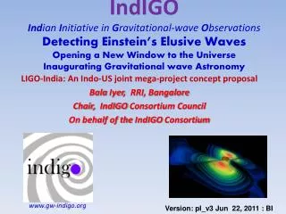
LIGO and I2U2: Making LIGO Physical Environment Data Available for Discovery-based Learning. Eric Myers with Fred Raab and Dale Ingram LIGO Hanford Observatory Hanford, Washington on behalf of the LIGO Scientific Collaboration. “Physics in a New Light” New York APS/AAPT Spring Symposium

E N D
LIGO and I2U2:Making LIGO Physical Environment Data Available for Discovery-based Learning Eric Myers with Fred Raab and Dale Ingram LIGO Hanford Observatory Hanford, Washington on behalf of the LIGO Scientific Collaboration “Physics in a New Light” New York APS/AAPT Spring Symposium West Point, New York 13-14 April 2007
Optics & Education (for “Physics in a New Light”, Joint NY APS/AAPT Spring Symposium 2007) LIGO interferometers are ultra-high precision optical devices (the largest on the planet,and largest optical instruments with their own overpass!) Operation of such ultra-high precision optics requires constant monitoring of the physical environment (seismic, magnetic, weather, ...) These data can be used by students and their teachers for discovery-based learning (real data, and possibly real research!) Astrophysics (for “Recent Advances in Astrophysics”, NY APS Fall Symposium 2007) LIGO seeks first to detect gravitational waves (non-optical waves), then To use gravitational waves (GW's) for astronomical observations Something for Everyone...
Gravitational Waves Rendering of space-time stirred by two orbiting black holes Matter curves space-time, and objects in “free-fall” (even photons) travel in “straight” paths in the curved space. Changes in space-time produced by moving a mass are not felt instantaneously everywhere in space, but propagates as a wave.
Gravitational Waves Travel at the speed of light “transverse” Two polarizations, “+” and “x” Tensor - quadrupole distortions of space-time Comparison with EM waves Electromagnetic Waves • Travel at the speed of light • “transverse” • Two polarizations: horizontal and vertical • Vector - dipole in both E and B • Solutions to Maxwell’s Eqns. • EM waves can be generated by a changingdipole charge distribution. • Solutions to Einstein’s Eqns. • Gravitational waves require changingquadrupole massdistribution.
Gravitational Waves Travel at the speed of light “transverse” Two polarizations, “+” and “x” Quadrupole distortions of space-time Comparison with EM waves Electromagnetic Waves • Travel at the speed of light • “transverse” • Two polarizations: horizontal and vertical • Dipole in both E and B • Solutions to Maxwell’s Eqns. • EM waves can be generated by a changingdipole charge distribution. • Solutions to Einstein’s Eqns. • Gravitational waves require changingquadrupole massdistribution.
Example: Binary Inspiral A pair of 1.4M neutron stars in a circular orbit of radius 20 km, with orbital frequency 400 Hz produces GW’s (a strain of amplitude h = L/L) at frequency 800 Hz. Wave frequency is twice the rotation frequency of binary. ( 1.4M binary inspiral provides a useful translation from dimensionless strain h to “reach” of the instruments, in Mpc )
Indirect Evidence for GW’s Taylor and Hulse studied PSR1913+16 (two neutron stars, one a pulsar) and measured orbital parameters and how they changed: The measured precession of the orbit exactly matches the loss of energy expected due to gravitational radiation. 17 / sec 17 / sec ~ 8 hr (Nobel Prize in Physics, 1993)
How might GW’s be produced? Producing significant gravitational radiation requires a large change in the quadrupole moment of a large mass distribution. The most likely astronomical sources are: • Coalescence of binary systems, such as the inspiral of pairs of neutron stars or black holes (NS-NS, NS-BH, BH-BH) CHIRP! • Continuous Wave sources, such as spinning (asymmetric!) neutron stars (“gravitational pulsars”), or body oscillations of large objects (neutron star “r-modes”). • Unmodeled Bursts from supernovae or other cataclysmic events (spherical symmetric = no GW -- requires changing quadrupole!) • Stochastic background from the early universe (Big Bang! Cosmic Strings,…) – a “cosmic gravitational wave background” (CGWB) • Something unexpected…!
Michelson Interferometer Measuring L in arms allows the measurement of the strain h = L/L, which is proportional to the gravitational wave amplitude h(t). (Larger L is better, and multiple reflections increase effective length.)
Laser Interferometer Gravitational wave Observatory LIGO Livingston Observatory (LLO) Livingston Parish, Louisiana L1 (4km) LIGO Hanford Observatory (LHO) Hanford, Washington H1 (4km) and H2 (2km) Funded by the National Science Foundation; operated by Caltech and MIT; the research focus for ~ 500 LIGO Scientific Collaboration members worldwide.
The LIGO Observatories • Adapted from “The Blue Marble: Land Surface, Ocean Color and Sea Ice” at visibleearth.nasa.gov • NASA Goddard Space Flight Center Image by Reto Stöckli (land surface, shallow water, clouds). Enhancements by Robert Simmon (ocean color, compositing, 3D globes, animation). Data and technical support: MODIS Land Group; MODIS Science Data Support Team; MODIS Atmosphere Group; MODIS Ocean Group Additional data: USGS EROS Data Center (topography); USGS Terrestrial Remote Sensing Flagstaff Field Center (Antarctica); Defense Meteorological Satellite Program (city lights). LIGO Hanford Observatory (LHO) H1 : 4 km arms H2 : 2 km arms 10 ms LIGO Livingston Observatory (LLO) L1 : 4 km arms
Power-recycled Fabry-Perot-Michelson suspended mirrors mark inertial frames antisymmetric port carries GW signal 10W Symmetric port carries common-mode info
What Limits Sensitivity? • Seismic noise & vibration limit at low frequencies • Atomic vibrations (thermal noise) inside components limit at mid frequencies • Quantum nature of light (shot noise) limits at high frequencies • Myriad details of the lasers, electronics, etc., can make problems above these levels
Technical Challenges • Typical Strains < 10-21 at Earth ~ 1 hair’s width at 4 light years • Understand displacement fluctuations of 4-km arms at the millifermi level (1/1000th of a proton diameter) • Control the arm lengths to 10-13 meters RMS • Detect optical phase changes of ~ 10-10 radians • Hold mirror alignments to 10-8 radians • Engineer structures to mitigate recoil from atomic vibrations in suspended mirrors • Do all of the above 7x24x365 S5 science run started 14 Nov 2005…
Educational use of LIGO PEM data • LIGO interferometers are ultra-high precision optical instruments! • Operation requires careful monitoring of the physical environment of the instruments. • PEM data (and data products derived from them, such as DMT BLRMS) can be used by students for inquiry-based learning projects: • LHO/Gladstone HS Program (1999-2004) • LIGO/I2U2 partnership (2005- ) PEM = “Physics Environment Monitoring” DMT = “Data Monitoring Tools” BLRMS = “Bandwidth Limited RMS” LIGO lingo:
LHO/Gladstone SST program A partnership between LIGO Hanford Observatory and Gladstone High School (near Portland, OR), supported by NSF, and administered (1999-2001) under the Student, Scientist, Teacher (SST) program run by Pacific Northwest National Lab (PNNL). (Continued informally until 2004.) • One teacher and three students spent 8 weeks at LHO in summers 1999 and 2000. • Science classes during school year involved a variety of projects aimed at understanding PEM seismic data transfered to GHS via Internet. • The students who had hands-on experience from a summer internship were a key resource. • Students met with a LIGO scientist via telecon every 3 weeks, and they visited the LHO site once during year. • Students built “demo” instruments which gave them hands-on experience with equipment without risk of breaking something.
LIGO/Gladstone results • A Sampling of Student Presentations (2002): • “Accelerometer Measurements through a LabView Interface” • “Running a LIGO Earth Tide Calculator at Gladstone” • “Processing LIGO Microseism Data in MS Excel” • “Processing Microseism Differences” • “Modeling the GHS Microseism Software using MATLAB” • “Twenty Years of Wave Heights and Wind Speeds from Pacific Ocean Buoys” • “Examining the Magnetic Field of the Earth in Southeastern Washington” • “Keeping the Wheels on the Bus--the Life of a Project Administrator” • Students wrote software to translate data into a form they could more easily read • Students viewed, modeled and analyzed data with Excel, MATLAB, perl, and C/C++ • Students found a correlation between microseism (sub-Hertz seismic motion) at LHO and wave heights reported by NOAA buoys off the Oregon and Washington coast: Wave height can be used as a “proxy” to predict overall microsism activity at Hanford • A microseism monitoring tool written by a GHS student was used for several years in the LHO control room until DMT Framework was developed and a new Monitor was written.
seism and wave height ((wave heights rescaled by 10-7)
Long-term microseism connection to ocean-wave activity Seasonal trend in microseism identified in early analysis (above) agrees qualitatively with ocean-buoy wave-height data (right)
QuarkNet spawns I2U2 • QuarkNet is a successful education project run by Fermilab E&O office • Network of in-school Cosmic ray detectors • Teaching materials for “e-Labs” (“one stop shopping”) • Collection of teachers making use of these • QuarkNet centers • QuarkNet organizers sought to extend the idea, so invited large physics experiments to join the effort: ATLAS, CMS, STAR, LIGO, with Adler Planetarium, U. Chicago • Aimed at leveraging Grid Computing for educational use • Title of project is “Interactions in Understanding the Universe” (I2U2) • Initial pilot funding from NSF for 2005-2006, extended for 2006-2007.
Einstein@Home • Searching through the data streams for evidence of gravitational waves from a periodic source at an arbitrary sky position requires an extremely large amount of computing power - more than available Beowulf clusters! • Einstein@Home uses the Berkeley Open Infrastructure for Network Computing (BOINC) to perform the search on a “small” chunk of data on a volunteer’s PC, all while displaying a nifty screensaver. Anybody can join: http://einstein.phys.uwm.edu/ • Web site includes discussion “forums” for interaction between users, and with project developers.
LIGO I2U2 Software Development --Goals -- • Provide easy access to LIGO environmental data (seismometers, magnetometers, tilt-meters, and weather stations) • Provide analysis tools with functionality and feel similar to those available to scientists in the LIGO control rooms (such as DMT, DTT, DataViewer, ilog) • Provide interface for use of “Grid” computing • Provide supporting tools for interaction and collaboration between students, teachers, e-Lab developers, and possibly LIGO scientists (SST)
Tool, LIGO Analysis (TLA) A web based Analysis Tool which has a user interface (adjustable!) similar to LIGO control room tools (DMT, DTT, & ROOT) and with the potential to provide much of the same functionality(with influences from LabView) Guest account: nyssaps / WestPoint Tutorial available as a PDF file
Analysis Tool Plot 8.0 and 6.7 magnitude earthquakes in South Pacific
Analysis Tool Status • Basic functionality now works to plot a single channel ("the circuit is complete"), but there is much more to be added. • Only minute-trend data, but soon to add second trends, raw data (256 Hz), and 10-min and 1-hr trends • Potential to incorporate DMT Monitor Framework, first to use existing "monitors" (e.g. Bandwidth filtering of magnetometer data, as is now done for seismic data), but also possibly to turn an interesting student-designed data transformation into a control room Monitor.
Electronic Logbook LIGO electronic logbook (the "ilog"). http://ilog.ligo-wa.caltech.edu/ilog ( reader / readonly ) I2U2 Prototype site Discussion / Logbook, Based on BOINC forums • File attatchments • Keyword classifications
Web site features Project glossary, using same software that runs Wikipedia RSS News subscription for project/server status
Teacher Activities Summer 2006 intern teacher John Kerr • Used second-trend data (from control room) to study p-wave/s-wave timing • Tested Analysis Tool when it was ready • Wrote TLA tutorial Teacher workshop, August 2006 At Hanford, included control room visits, training in use of Analysis Tool and discussion of classroom activities Initial student classroom trials in 2006-07
2006-2007 activities • Improvments to the Analysis Tool • Create “e-Lab” teaching materials for I2U2 site QuarkNet flow diagram • LHO Teacher internships for Summer 2007 • LHO Teacher Workshop planned for Summer 2007
Conclusions • LIGO interferometers are ultra-high precision optical devices • Operation of LIGO instruments requires monitoring of the physical environment • PEM and related data can be used by students and their teachers for discovery based education. + = "A great discovery solves a great problem, but there is a grain of discovery in the solution of any problem." - G. Polya, 1944 Try it out: http://tekoa.ligo-wa.caltech.edu/tla (user: nyssaps / password: WestPoint)