Download
1 / 43
440 likes | 695 Views
Controller Design for a Linearly Actuated Suspension System (cdlass). Dan Altman, Tim Reilley & Joseph Sholl Advisors: Prof. Gutschlag & Prof. Anakwa. Presentation Outline . Background Applications Motivation Project Summary Disturbance Analysis & System Modeling

E N D
Controller Design for a Linearly Actuated Suspension System (cdlass) Dan Altman, Tim Reilley & Joseph Sholl Advisors: Prof. Gutschlag & Prof. Anakwa
Presentation Outline • Background • Applications • Motivation • Project Summary • Disturbance Analysis & System Modeling • Hardware, Software, and Circuitry
Background 1991 - Pneumatic Active Suspension System by Dion Thomas and Scott Jones, advisor: Dr. Anakwa 2002 - Dr. Anakwa publishes "Development and Control of a Prototype Pneumatic Active Suspension System" (with students), IEEE Transactions on Education, Vol. 45, No. 1, February 2002, pp. 43-49. 2006 – Active Suspension System by Blake Boe and Tyson Richards
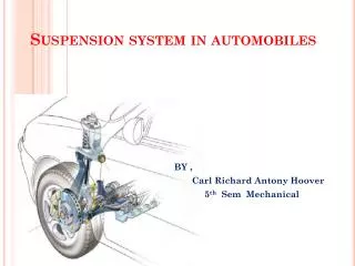
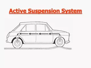
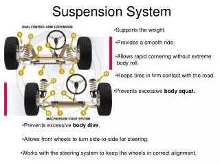
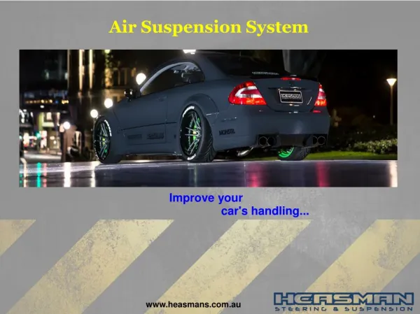
Applications • System could be implemented in: • Seat inside of the cab • Under the cab
Motivation • Shared Interest in: • Electromechanical systems • Power electronics • Controls • Experience using LabVIEW software
Project Summary H-bridge Design Controller design using data from position sensor Use of LabVIEW software Creation of LabVIEW tutorial
Project Goals • Reintegrate the linear actuator and H-bridge hardware into the suspension system due to the unavailability of the H-bridge hardware used previously • Model the system characteristics of the linear actuator • Implement National Instrument’s hardware and software (LabViewTM) to provide data acquisition and power electronics control
Project Goals cont. • Implement a feedback position controller using National Instrument’s hardware and software (LabVIEWTM) to minimize the error • Create a tutorial for the use of National Instrument’s hardware and software (LabViewTM)
Performance Specifications • A controller capable of driving the linear actuator to maintain a midpoint level, minimizing a displacement for a disturbance with a frequency of up to 5 Hz • Minimized displacement of the cab from the midpoint to ± ⅛” (3.175 mm) with no load • Minimized displacement of the cab from the midpoint to ± ¼” (6.35 mm) with a load
Previous Work on Active Suspension System • Replaced the pneumatic actuator with an electric linear actuator • Modeled the H-bridge in PSPICE • Integrated the linear actuator and H-bridge hardware into the suspension system • Modeled the system including the linear actuator using Simulink • Implemented open and closed loop controllers to minimize the error displacement to ¼ [in] with a 1 [in] disturbance
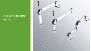
Physical System Load (mass) Position Sensor Linear Actuator Camshaft
Controller Flow Chart Position Sensor (Platform) Controller Position Sensor (Actuator) Forward/Reverse Off/On (Brake) PWM Run/Stop H-Bridge / Linear Actuator NI Hardware DAC ADC Disturbance Scope
Linear Actuator • Uses controller information from LabVIEW and potentiometer in order react to disturbances • Relationship between torque and applied force:
Linear Actuator/System Test • Based on the relationship between torque and applied force we derived the following equation to determine Tc and b:
Linear Actuator/System Test Trial 1: 20 Lbs (or 9.07 kgs) of weights used Steady-State Approx. 20.5 V
Linear Actuator/System Test Trial 2: 25 Lbs (or 11.34 kgs) of weights used Steady-State Approx. 49.2 V
Linear Actuator/System Test • Based on the previous group’s work: kE=0.382[V/rad/sec] so: • Trial 1: ω = 20.5 [V] / .382 [V/rad/sec] = 53.67[rad/sec] • Trial 2: ω = 49.2 [V] / .382 [V/rad/sec] = 128.80[rad/sec] • Using simultaneous equation solver: • Tc = 0.09304b = 7.55 X 10⁻⁴
Disturbance Control • AC motor drives the cam • Variable Frequency Drive, Controls the speed of the AC motor • Single elliptical cam shape causes the disturbance while rotating
OriginalH-bridge and Gate Driver Hardware IRF640N Power MOSFET 6N137 Logic Gate Optocouplers We will utilize: • Four IRF640N Power MOSFETs • Two IR2110 High and Low Side Drivers • Four 6N137 High Speed 10MBit/s Logic Gate Optocouplers IR2110 IR2110 Gate Driver
Revised H-bridge and Gate Driver Hardware We will utilize: • Four (4) HCPL 3120 Gate Drive Optocouplers • One (1) IGBT Full-bridge Power Module • Reason for Change: • HCPL 3120 more robust, fewer chips, built-in optocoupling • MOSFET’s could not handle large current spikes IGBT Full-bridge Power Module HCPL 3120 • Gate Drive Optocoupler
H-Bridge Circuit H2 H1 L1 L2
H-Bridge Circuit: Forward Mode H1 H2 L1 L2
H-Bridge Circuit: Reverse Mode H1 H2 L2 L1
National Instrument Hardware •NI cDAQ-9174 NI CompactDAQ 4-slot USB 2.0 Chassis, 9 V - 30 V Input Voltage Range • • NI 9401 8-Channel Ultra-high Speed Digital I/O Module • NI 9221 8-Channel 12-Bit Analog Input Module
Motor Modeling Simulations Angular Velocity Linear Velocity Linear Acceleration Simulink LabVIEW
Front Panel of PWM Generator Let Amplitude = A Duty Cycle = (A-1)/A
Front Panel of PWM Generator Disturbance Signal Processed Error Signal
Overview • Working H-Bridge design • System model created and simulated in LabVIEW • PWM signal generator created in LabVIEW • Data acquisition merged with PWM signal generator in LabVIEW
Future Work • Integration of H-Bridge and controller in LabVIEW • Expanding experience with National Instruments hardware and software such as using RIO and additional software modules
References References [1] Blake Boe and Tyson Richards. “Active Suspension System”, Senior Project, Electrical and Computer Engineering Department, Bradley University, May 2006, http://cegt201.bradley.edu/projects/proj2006/actss/ [2] IDC Motion EC2 Series Linear Actuator Data Sheet [3] National Instruments Hardware Data Sheets [4] Anakwa, Dr. Winfred, "Development and Control of a Prototype Pneumatic Active Suspension System" (with students), IEEE Transactions on Education, Vol. 45, No. 1, February 2002, pp. 43-49.
Background John Deere introduced the hydraulic powered actuated active suspension seat in 2001